
A Ventilation Device That Can Reduce Noise

A ventilation device and noise technology, which can be used in ventilation layout and other directions to solve problems such as noise pollution

Active Publication Date: 2016-08-17
HARBIN INST OF TECH
View PDF3 Cites 0 Cited by
  • Summary
  • Abstract
  • Description
  • Claims
  • Application Information

AI Technical Summary

Problems solved by technology

[0003] The present invention solves the problem that the existing ventilator introduces outdoor noise into the room while ventilating the room, which brings noise pollution to the room, and further proposes a ventilation device that can reduce noise

Method used


Image

  • A Ventilation Device That Can Reduce Noise

Examples


specific Embodiment approach 1

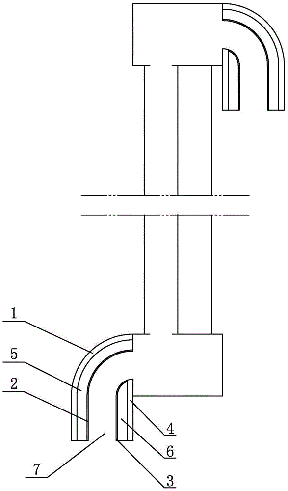
[0007] Specific implementation mode one: combine figure 1 Describe this embodiment, a ventilation device that can reduce noise described in this embodiment includes an outer support plate 1, a first micro-perforated plate 2, a second micro-perforated plate 3 and an inner support plate 4, the outer support plate 1 is an arc Shaped plate body, the outer support plate 1 and the inner support plate 4 are vertically arranged, the first micro-perforated plate 2 and the second micro-perforated plate 3 are vertically arranged between the outer support plate 1 and the inner support plate 4, the outer support plate 1 and the inner support plate 4 The first micro-perforated plate 2 forms the first cavity 5 , the inner support plate 4 and the second micro-perforated plate 3 form the second cavity 6 , and the first micro-perforated plate 2 and the second micro-perforated plate 3 form the ventilation channel 7 .

specific Embodiment approach 2

[0008] Specific implementation mode two: combination figure 1 The present embodiment is described. The ventilation opening of the ventilation passage 7 of the noise-reducing ventilation device described in the present embodiment faces vertically downward. Other components and connections are the same as those in the first embodiment.

specific Embodiment approach 3

[0009] Specific implementation mode three: combination figure 1 To illustrate this embodiment, the outer support plate 1 and the inner support plate 4 of a ventilation device capable of reducing noise described in this embodiment are both made of plastic or metal. Other compositions and connections are the same as those in Embodiment 1 or 2.

[0010] working principle

[0011] When the present invention is in use, a ventilation device is horizontally arranged at the upper end of the outside of the window frame, and a ventilation device is horizontally arranged at the lower end of the inside of the window frame. The cavity between the two glasses, the cavity on the top edge of the window frame, and the ventilation channel 7 of the ventilation device located inside the window frame form a ventilation channel, and the outside air enters the room through the ventilation channel, and the first micro-perforated plate 2 and The second micro-perforated plate 3 effectively reduces ex...


PUM


Abstract

The invention relates to ventilation devices, in particular to a ventilation device capable of lowering noise. The ventilation device capable of lowering noise aims at solving the problem that when an existing ventilation device is used for ventilating a room, noise pollution is brought into the room due to the fact that outdoor noise is introduced into the room. The ventilation device comprises an outer support plate, a first micro-perforation plate, a second micro-perforation plate and an inner support plate. The outer support plate is a circular arc plate. The outer support plate and the inner support plate are vertically arranged. The first micro-perforation plate and the second micro-perforation plate are vertically arranged between the outer support plate and the inner support plate. A first cavity is formed by the outer support plate and the first micro-perforation plate. A second cavity is formed by the inner support plate and the second micro-perforation plate. A ventilation passage is formed by the first micro-perforation plate and the second micro-perforation plate. The ventilation device capable of lowering noise is applied to the building field.

Description

technical field [0001] The invention relates to a ventilation device, in particular to a ventilation device capable of reducing noise, and belongs to the construction field. Background technique [0002] In architecture, a window is an opening made in a wall or roof to allow light or air to enter a room. When the windows are closed at night, the ventilator will introduce natural ventilation into the room, but the ventilator also introduces the outdoor noise into the room while introducing the outdoor natural wind, which brings noise pollution to the room. Contents of the invention [0003] In order to solve the problem that the existing ventilator introduces outdoor noise into the room while ventilating the room, and brings noise pollution to the room, the invention further proposes a ventilation device capable of reducing noise. [0004] The technical scheme adopted by the present invention to solve the above-mentioned problems is: the present invention comprises an oute...

Claims


Application Information

Patent Timeline
Patent Type & Authority Patents(China)
IPC IPC(8): E06B7/02
Inventor 康健
Owner HARBIN INST OF TECH
Learn More