
A bionic swimming propeller and swimming propulsion method

A propeller and base technology, applied in swimming aids, swimming fins, swimming fins, etc., can solve the problems of bound hands and feet, complex structure, swimming speed limit, etc., to reduce forward resistance, increase the area of ​​action, improve The effect of swimming speed

Inactive Publication Date: 2016-04-06
刘雨婷
View PDF4 Cites 1 Cited by
  • Summary
  • Abstract
  • Description
  • Claims
  • Application Information

AI Technical Summary

Problems solved by technology

When people swim, they mainly rely on the upper arm swing and the reaction force generated between kicking and the water to move forward. Due to the particularity of the human body structure, the swimming speed of people in the water is limited. The functional area between the hands and feet, but at the same time it also restricts other functions of the hands and feet
At present, the propeller used to help speed up swimming in the background technology, such as Chinese invention patent application 2013107428326, "a swimming propeller", uses batteries, motors, propellers, etc. for auxiliary propulsion. The structure is complex, the cost is high, and additional batteries are required as Power; Invention patent 2010202973417, "swimming propeller", does not require batteries, adopts a frame and blade structure, but the structure is unreasonable, the propulsion effect is not obvious, the operation is troublesome, and the practicability is poor

Method used


Image

  • A bionic swimming propeller and swimming propulsion method
  • A bionic swimming propeller and swimming propulsion method
  • A bionic swimming propeller and swimming propulsion method

Examples


Embodiment Construction

[0026] The present invention will be further described through the embodiments below in conjunction with the accompanying drawings.

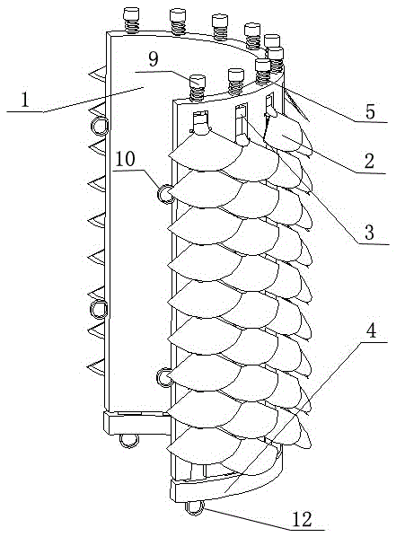
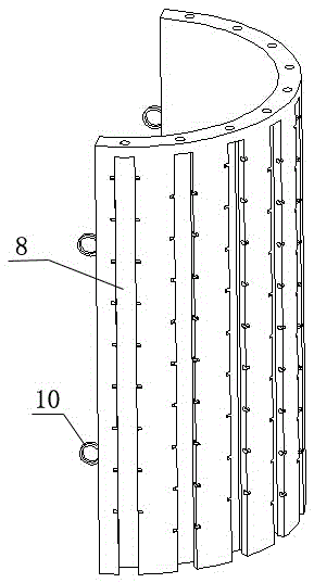
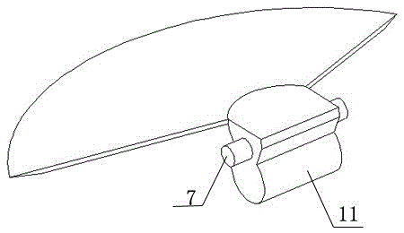
[0027] A bionic swimming propeller, comprising a base body 1, scales 2, pull rods 3, a bottom ring 4 and a spring 5, the surface of the base body is provided with a plurality of longitudinal grooves 8, and the inner walls of both sides of the grooves are provided with corresponding shaft holes; each There is a pull rod in each groove, the pull rod is embedded in the groove and slides up and down along the groove, one end of the pull rod 3 passes through the top of the substrate, and is covered with a spring 5, and the pull rod is provided with multiple transverse grooves 6; each The scale 2 is provided with a connecting shaft 7, the connecting shaft is arranged above the groove 6 of the pull rod, the two ends of the connecting shaft are stuck on the shaft hole in the groove of the base body, and each scale is hinged with the base body through the...


PUM


Abstract

The invention relates to a bionic swimming propeller and a swimming propelling method, and belongs to the technical field of swimming equipment and swimming propelling methods. According to the technical scheme, a plurality of longitudinal grooves (8) are formed in the surface of a base body (1), and corresponding shaft holes are formed on the inner walls on the two sides of each groove; a pull rod (3) is arranged in each groove, is embedded in the groove and slides up and down in the groove, one end of each pull rod penetrates out of the upper portion of the base body and is sleeved with a spring (5), and each pull rod is provided with a plurality of transverse grooves (6); a connecting shaft (7) is arranged on each scale (2) and located above the corresponding groove in the corresponding pull rod, and the two ends of each connecting shaft are clamped in the shaft holes in the corresponding groove of the base body; a bottom ring (4) is arranged below the base body and matched with the base body in shape. The bionic swimming propeller simulates the structure of scales and is simple in structure, convenient to use and practical, the bionic swimming propeller is tied to the crus when a user swims, and the scales are opened when the user drives the legs, so that the action area between the crus and water is increased; the scales are closed when the user withdraws the legs, so that advance resistance is reduced, and then swimming speed is increased.

Description

technical field [0001] The invention relates to a bionic swimming propeller and a swimming propulsion method, belonging to the technical field of swimming equipment and swimming propulsion methods. Background technique [0002] Swimming like a fish in water is a human dream. When people swim, they mainly rely on the upper arm swing and the reaction force generated between kicking and the water to move forward. Due to the particularity of the human body structure, the swimming speed of people in the water is limited. The functional area of ​​the body is wide, but at the same time it also restricts other functions of the hands and feet. At present, the propeller used to help speed up swimming in the background technology, such as Chinese invention patent application 2013107428326, "a swimming propeller", uses batteries, motors, propellers, etc. for auxiliary propulsion. The structure is complex, the cost is high, and additional batteries are required as Power: Invention pate...

Claims


Application Information

Patent Timeline
Patent Type & Authority Patents(China)
IPC IPC(8): A63B31/12A63B31/10A63B35/10
Inventor 刘雨婷
Owner 刘雨婷
Learn More