A chair for treating lumbar diseases
A technology of chair and lumbar spine, applied in medical science, fractures, etc., can solve the problems of inconvenient use of autologous traction bed, unstable fixation of thoracic traction belt, upward sliding of thoracic traction belt, etc., and achieve good pain relief effect without difficulty Discomfort, lumbar pain relief effect
- Summary
- Abstract
- Description
- Claims
- Application Information
AI Technical Summary
Problems solved by technology
Method used
Image
Examples
Embodiment 1
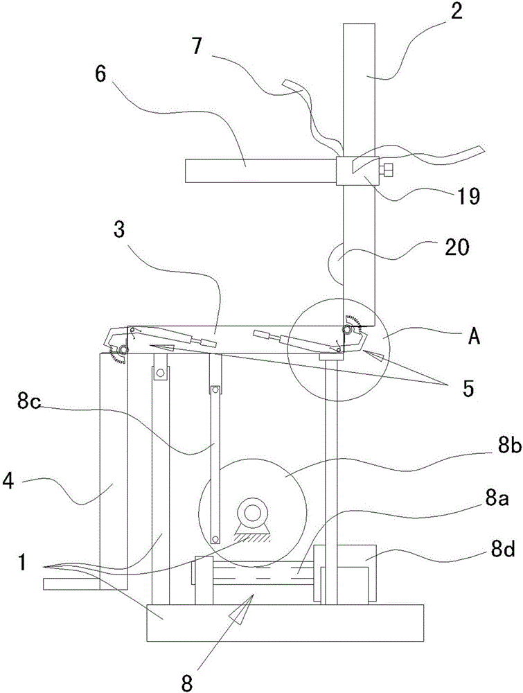
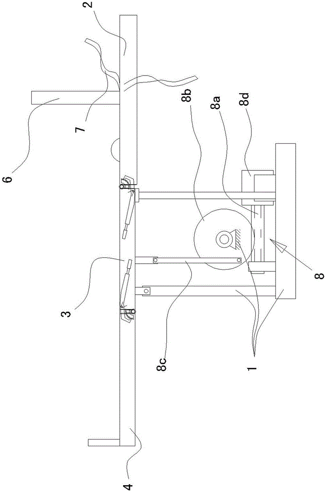
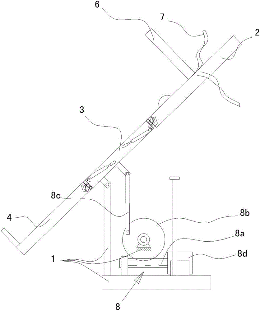
[0023] Such as figure 1 , 2, and 3, the present invention includes a base 1, a backrest 2, a seat plate 3, an apron 4, and a locking mechanism 5; 8. There are two hinge points at the front end of the seat plate 3, and the previous hinge point at the front end of the seat plate 3 is rotatably connected to the base 1. The electric rotating table 8 includes a screw rod 8a driven by a motor 8d and a gear driven by the screw rod. 8b, the swing arm driven by the gear 8b (or just a big gear 8b as shown in the embodiment), the two ends are respectively hinged with the last hinge point of the seat plate 3 and the swing arm (or the eccentric position of the big gear 8b) The connecting rod 8c, the locking mechanism 5 is a manual locking mechanism, such as image 3 As shown, the locking mechanism 5 includes an arc-shaped plate 5b fixed on the outer edge of the backrest 2 with several slots 5a, a hook 5d driven by the swing arm 5c, and the hook 5d faces the slots of the arc-shaped plate 5...
Embodiment 2
[0030] Such as Figure 4 As shown, this embodiment is based on Embodiment 1. The skirt plate 4 includes a fixed part 4a hinged on the seat plate 3, a swing part 4b connected with the fixed part 4a through a power swing mechanism 21, and the power swing mechanism 21 It is arranged on the fixed part 4 a, and the swing part 4 b is hinged to one end of the swing arm 21 a of the power swing mechanism 21 . The swing part 4b is slidably arranged on the slideway 4d fixedly connected with the fixed part 4a through the slide rail 4c. The power swing mechanism 21 includes a screw mandrel 21c driven by a motor 21b, a gear 21d meshing with the screw mandrel 21c, and a swing arm 21a The other end of the eccentrically hinged on the gear 21d.
Embodiment 3
[0032] Such as Figure 5 As shown, the locking mechanism 5 is an electric locking mechanism, and the locking mechanism 5 includes a parallelogram mechanism 10 whose four sides are hinged together, a drive power 11 that drives two opposite angles 10a of the parallelogram mechanism 10 to move relatively, and the seat plate 3 is connected in parallel On the upper side 10b of the quadrilateral mechanism 10, the backrest 2 is connected to one side 10c of the parallelogram mechanism 10, and the skirt plate 4 is connected to the other side 10d of the parallelogram mechanism 10; The motor 11a on a pair of corners 10a, the screw mandrel 11b driven by the motor 11a, the screw mandrel cover 11c arranged on the other diagonal 10a of the parallelogram mechanism 10, the screw mandrel 11b is connected on the screw mandrel cover 11c.
[0033] When working, the motor 11a drives the screw rod 11b to rotate, and the screw rod 11b drives the screw rod cover 11c to move, so that the parallelogram ...
PUM
 Abstract
Description
Claims
Application Information
 - R&D
- Intellectual Property
- Life Sciences
- Materials
- Tech Scout
- Unparalleled Data Quality
- Higher Quality Content
- 60% Fewer Hallucinations
Browse by: Latest US Patents, China's latest patents, Technical Efficacy Thesaurus, Application Domain, Technology Topic, Popular Technical Reports.
© 2025 PatSnap. All rights reserved.Legal|Privacy policy|Modern Slavery Act Transparency Statement|Sitemap|About US| Contact US: help@patsnap.com


