
Rope winch

A technology of winches and rope drums, which is applied in the field of lifting device winches, and can solve problems such as restrictions and large lateral force of rope loops

Active Publication Date: 2014-11-12
LIEBHERR COMPONENTS BIBERACH GMBH
View PDF12 Cites 21 Cited by
  • Summary
  • Abstract
  • Description
  • Claims
  • Application Information

AI Technical Summary

Problems solved by technology

But the length of the rope that can be wound is finally limited here, because the number of separations has to be larger with a relatively long rope, but this will lead to a large drum length and drum width. At this time, at the side Increasingly inclined rope take-in angles towards the end side of the rope drum in the subwinding zone will result in an increasing lateral force acting on the rope loop

Method used


Image

  • Rope winch
  • Rope winch
  • Rope winch

Examples


Embodiment Construction

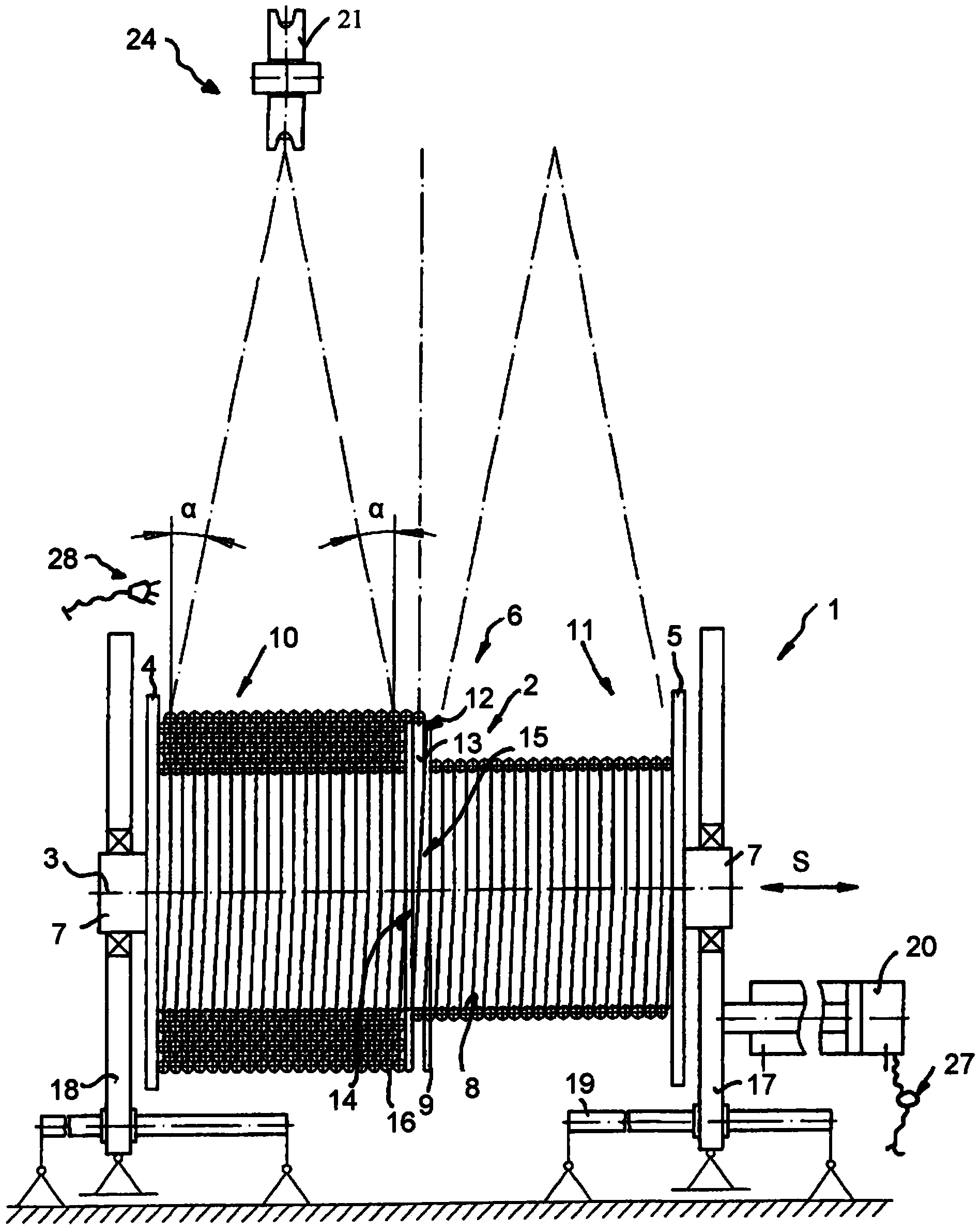
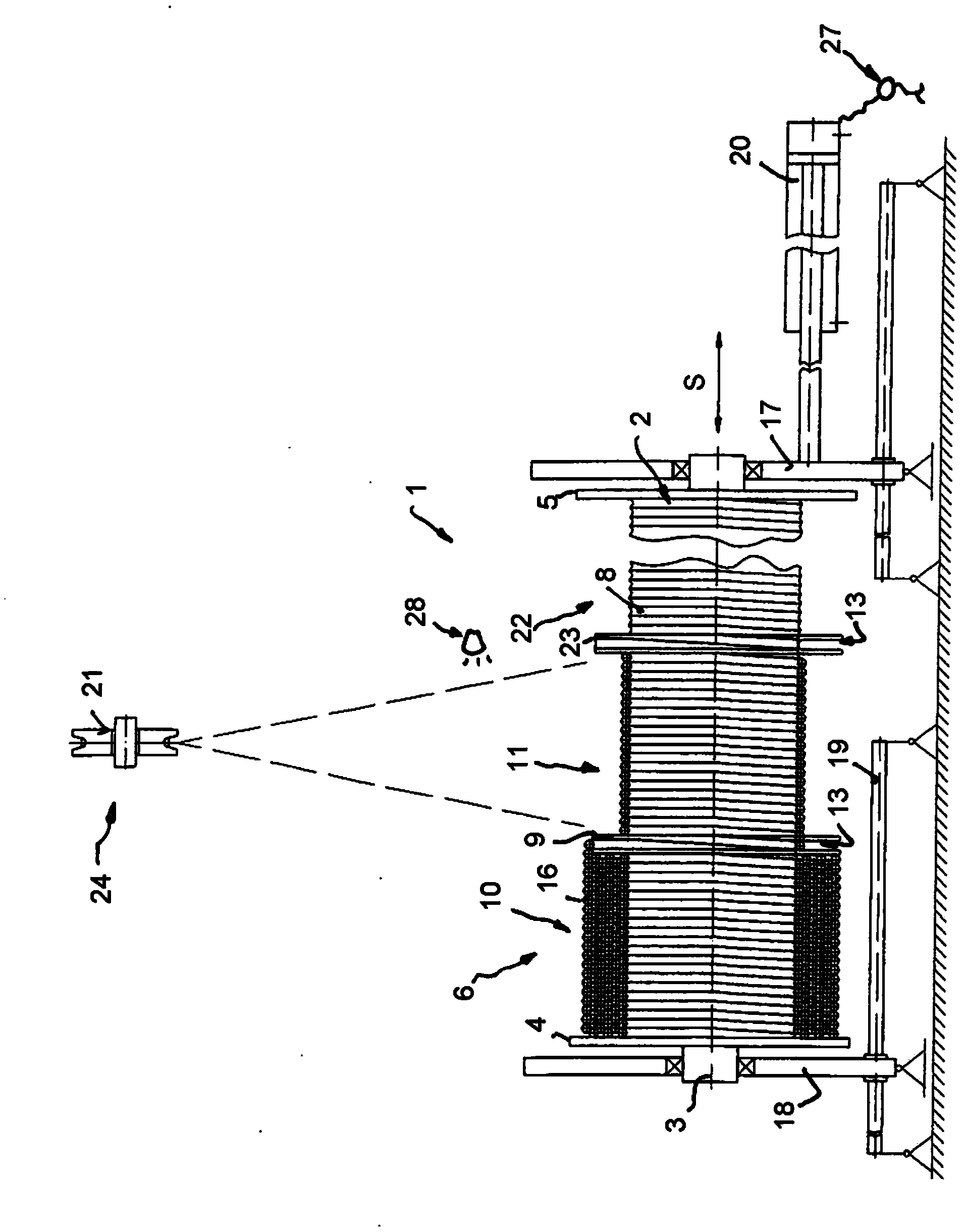
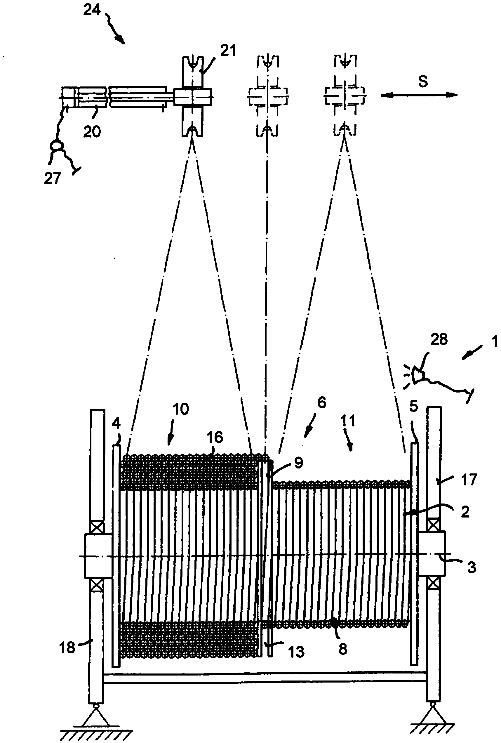
[0042] The winch 1 as shown in the figure comprises a substantially cylindrical rope drum 2, two flat retaining rings 4, 5 extending radially along the axis of rotation 3 of the rope drum are arranged on both ends of the rope drum, The winding area 6 of the rope drum 2 is defined between the flat retaining rings. In a manner known per se, the bearing end and / or the drive end 7 in the form of an axially protruding shaft end can be arranged on the rope drum 2, and the winch 1 can be mounted together with them on a lifting device such as a crane and as follows Supported longitudinally as explained above.

[0043] Such as figure 1 As shown, the peripheral surface of the rope reel 2 is equipped with a rope groove 8, and the rope groove extends helically outside the rope reel 2 in a threaded form to guide the rope to be wound on the rope reel 2, specifically the first rope. layer.

[0044] Such as figure 1 As shown, the winding area 6 of the rope drum 2 is divided into two sub-c...


PUM


Abstract

The invention relates to a rope winch, in particular a hoisting winch, comprising a rope drum, the winding area of which is delimited by two lateral flanged wheels, wherein at least one further flanged wheel is provided between the lateral flanged wheels for dividing the winding region into at least two partial winding regions, wherein the rope can be guided across the specified further flanged wheel into the at least two partial winding regions. The rope drum and / or one lateral rope guidance can be moved transversely to the longitudinal direction of the incoming / outrunning rope approximately in the longitudinal drum direction and / or the rope drum can be adjusted in the angle position thereof in relation to at least one lateral axis perpendicular to the drum longitudinal direction.

Description

technical field [0001] The invention relates to a winch, and in particular a hoist winch, having a rope drum whose winding area is delimited by two transverse flat rings, between which at least one additional flat stop is arranged The loop serves to divide the winding area into at least two sub-coiling areas into which the rope can be guided past said additional flat collar. Background technique [0002] Winding problems often arise in winches when there are many coils of rope side by side on the drum and the rope should be wound in multiple layers. At this point the problem becomes especially severe when the rope is wound with no or only a little pretension. If, for example, as may occur during demolition operations or demolition operations, a higher rope tension suddenly acts on a loosely wound rope package, the loosely wound rope package may be moved, where the rope is easily stuck in its position. between the underlying winding layers. This problem is all the more ser...

Claims


Application Information

Patent Timeline
Patent Type & Authority Applications(China)
IPC IPC(8): B66D1/30B66D1/36B66D1/38B66D1/39B66D1/48
CPCB66D1/30B66D1/365B66D1/38B66D1/48B66D1/39B66D1/26
Inventor N·豪斯拉登G·海普
Owner LIEBHERR COMPONENTS BIBERACH GMBH
Learn More