
A radar detection method and device for obtaining low-altitude wind profile

A detection device and detection method technology, applied in the field of radar detection, can solve the problems of low price, inability to obtain low-altitude wind profiles in close blind areas, etc., and achieve the effects of high resolution, high average power, and avoiding spectrum broadening

Active Publication Date: 2016-06-08
航天新气象科技有限公司
View PDF4 Cites 4 Cited by
  • Summary
  • Abstract
  • Description
  • Claims
  • Application Information

AI Technical Summary

Problems solved by technology

[0053] The object of the present invention is to provide a kind of radar detection method and device that obtains low-altitude wind profile, solve adopting boundary layer wind profile radar or adopting FMCW meteorological radar to occur close range blind spot, can't obtain the low-altitude wind profile below 50m (wind) Field wind direction and wind speed data), obtain low-altitude wind profile data including the near-surface layer, and carry out low-altitude detection of the near-surface layer and the atmospheric boundary layer. The minimum detection height is 50m to 10m, making up for existing radar detection methods and The lack of low-altitude detection capability of the device provides basic data for the study and prediction of the dynamic structure and changes of the low-altitude atmospheric wind field. Provide low-cost, cost-effective high-resolution low-altitude atmospheric detection equipment for important applications such as early warning

Method used


Image

  • A radar detection method and device for obtaining low-altitude wind profile
  • A radar detection method and device for obtaining low-altitude wind profile
  • A radar detection method and device for obtaining low-altitude wind profile

Examples


specific Embodiment

[0171] Specific embodiments: the working frequency is 2945MHz, which refers to the center frequency of the FMCW sweeping range, the sweeping width of the transmitted signal is 40MHz, and the effective sweeping width is 30MHz.

[0172] image 3 It is a schematic diagram of sawtooth wave frequency sweep working mode. see image 3 , the effective sweep width refers to the sweep width within the sampling time T, which determines the distance resolution. The frequency sweep width T2 of the actual transmitted signal is greater than T effective frequency sweep width. The T1 time represents the delay determined by the range, and a sufficiently large T1 is required to ensure the detection height measurement range.

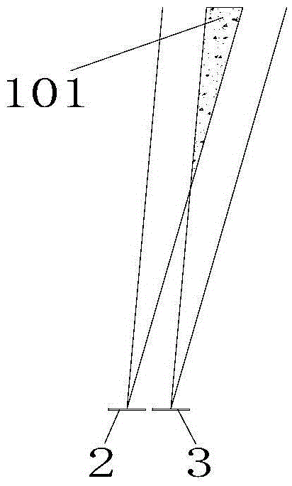
[0173] Figure 2b Represents the target 102 of the high-resolution distance unit, the target thickness is relatively small, for the same height, such as 10m height, in the echo signal of the detection unit with the minimum height of 10m, the echo signal of the high-reso...


PUM


Abstract

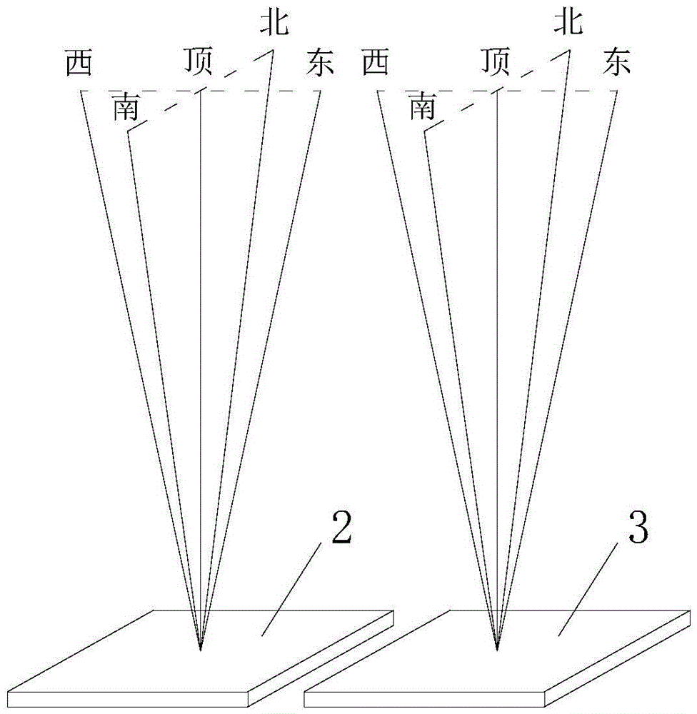
The invention relates to a radar detection technology, and provides a method and a device for detecting radar acquiring low-altitude wind profiles through combination of a frequency-modulated continuous-wave radar technology and a wind profile radar technology against the poor low-altitude detection capability of the existing equipment. One phased-array antenna is adopted to transmit serrated linear frequency-modulated continuous waves, and the other phased-array antenna is adopted to receive echo signals, thus forming a dual-antenna working mode of continuous-wave radar. The array surfaces of the two antennas are horizontally placed side by side with opening surfaces facing upward. Time-sharing scanning is carried out to form five detection wave beams which are the same with wind profile radar, and detection signals and data of the five wave beams are processed in the same way that signals and data of wind profile radar are processed so as to obtain a low-altitude wind profile of which the smallest height can be as small as 50m to 10m and other basic data products. A low-altitude continuous-wave wind measuring radar manufactured by adopting the method and the device of the invention has a wide range of applications.

Description

technical field [0001] The invention relates to the technical field of radar detection, in particular to a radar detection method and device for obtaining low-altitude wind profiles. Background technique [0002] The Earth's atmosphere is divided into layers according to its thermal structure: troposphere, stratosphere, mesosphere, and thermosphere. The atmospheric boundary layer is the air layer closest to the ground in the troposphere, where there are turbulent flows of various scales, and the diurnal variation of meteorological elements is significant. When the thickness of the boundary layer is low, it is only tens of meters, and when it is high, it can reach several kilometers, with a typical value of 1km to 3km. The atmospheric boundary layer is further divided into near-surface layer, mixed layer and top inversion layer. The location of the top of the boundary layer is roughly in the middle of the top inversion layer. [0003] Turbulent flow is the main form of mot...

Claims


Application Information

Patent Timeline
Patent Type & Authority Patents(China)
IPC IPC(8): G01S13/95G01S7/02
CPCG01S7/35G01S13/95G01S13/956Y02A90/10
Inventor 沈江林孙文玲王嘉祥魏艳强石瑞英李隽张颖杨川任迎新
Owner 航天新气象科技有限公司
Learn More