
A Model Rope Support System Realizing Virtual Flight in Wind Tunnel

A technology for supporting systems and aircraft models, applied in the field of aircraft models to achieve the effects of improving measurement accuracy, increasing usable value, and being easy to install

Active Publication Date: 2016-06-15
XIAMEN UNIV
View PDF7 Cites 2 Cited by
  • Summary
  • Abstract
  • Description
  • Claims
  • Application Information

AI Technical Summary

Problems solved by technology

[0007] The purpose of the present invention is to solve the measurement problem of the aerodynamic parameters of the model when the cable traction parallel mechanism is applied to the wind tunnel test, to provide a simple structure, convenient installation, strong versatility, and little interference to the flow field, which can be popularized and applied to various wind tunnel tests A model rope support system with a built-in six-component force balance that can realize virtual flight in a wind tunnel

Method used


Image

  • A Model Rope Support System Realizing Virtual Flight in Wind Tunnel
  • A Model Rope Support System Realizing Virtual Flight in Wind Tunnel
  • A Model Rope Support System Realizing Virtual Flight in Wind Tunnel

Examples


Embodiment 1

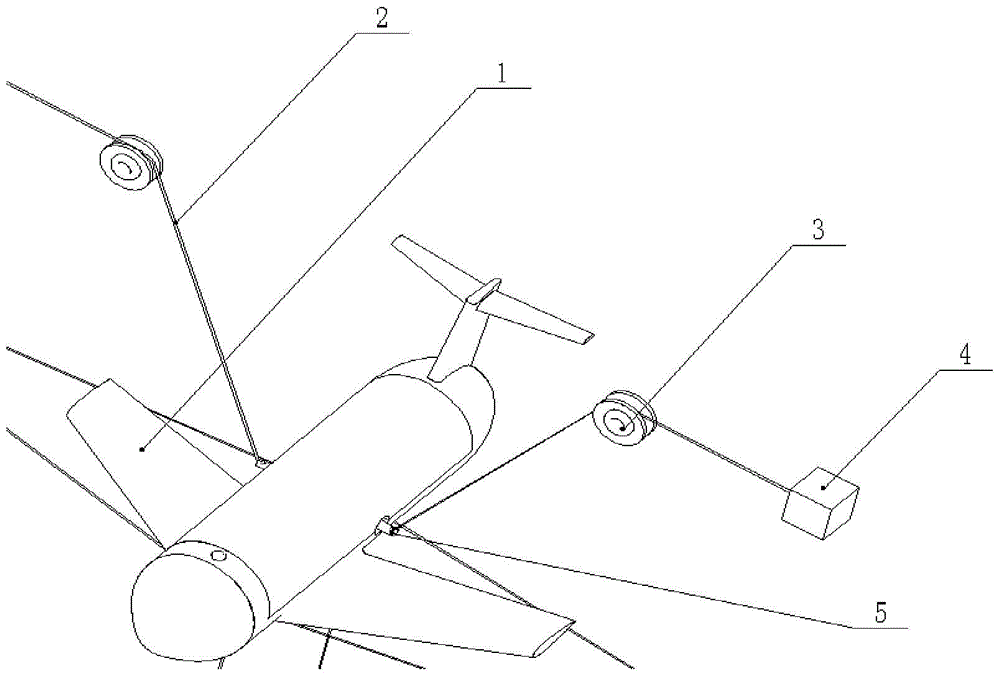
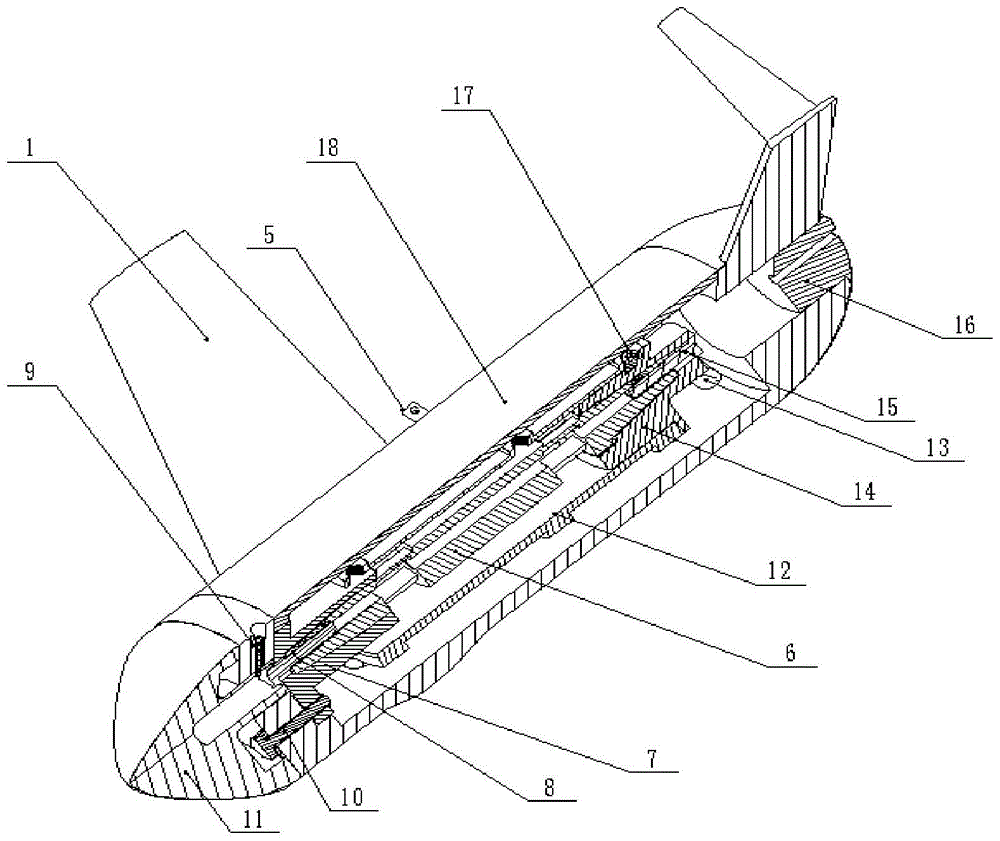
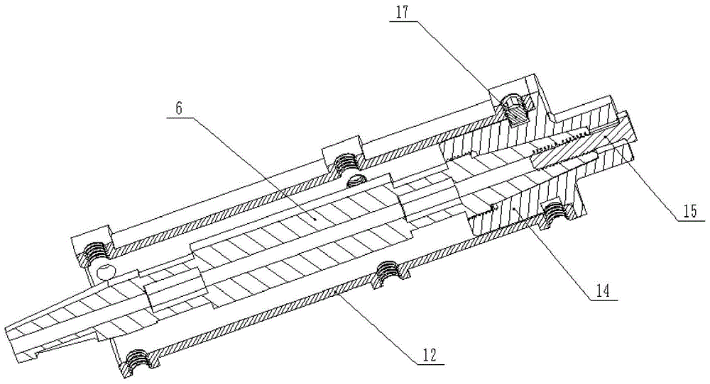
[0024] The embodiment of the present invention is provided with aircraft model 1, rod type six-component force balance 6, front taper sleeve 7, rear taper sleeve 14, sleeve 12 and pole 5, and aircraft model 1 is pulled and suspended by traction rope 2, and traction rope 2 One end is connected to winch motor assembly 4 by pulley 3, and the other end of traction rope 2 is connected with strut 5, is used for suspending and supporting aircraft model 1, and rod type six-component force balance 6 is located in aircraft model 1, and rod type six The force component balance 6 is coaxial with the aircraft model 1, the front end of the rod-type six-component force balance 6 is connected with the front cone sleeve 7 through 8, and the rear end of the rod-type six-component force balance 6 is connected with the rear cone sleeve 14 through a bolt 15, and the sleeve The cylinder 12 is fixedly connected to the rear taper sleeve 14 through bolts 17, the sleeve 12 is installed parallel to the r...

Embodiment 2

[0032] Figure 4 It is a schematic diagram of Embodiment 2 of the present invention. The installation and fixing methods of the airplane model and the rod-type six-component force balance assembly are the same as in Embodiment 1. combine Figure 5 Example cross-sectional view with Figure 6 It can be seen that the difference between embodiment 2 and embodiment 1 is that there is no tail plug, and the rear taper sleeve 14 located at the rear end of the balance is extended with an extended hollow pipe 19 extending out of the tail. Some small poles 5 are arranged on the prolongation hollow pipe 19, are used for tying the traction rope.

[0033] Embodiment 2 is an extension of the application of Embodiment 1. Different embodiments can be adopted according to the aerodynamic layout of the model appearance and the test purpose requirements, or the plug 16 of embodiment 1, or the extended hollow tube 19 added in embodiment 2, to change the layout of the rope system, thereby chang...


PUM


Abstract

A model rope support system capable of realizing virtual flight in a wind tunnel relates to an aircraft model. It is equipped with an airplane model, a rod-type six-component force balance, a front cone sleeve, a rear cone sleeve, a sleeve and a pole. The airplane model is pulled and suspended by a traction rope. One end of the traction rope is connected to the winch motor assembly through a pulley, and the other end of the traction rope One end is connected with the support rod, which is used to hang and support the aircraft model. The rod-type six-component force balance is arranged in the aircraft model. The rod-type six-component force balance is coaxial with the aircraft model. The front end of the rod-type six-component force balance passes through the Taper sleeve connection, the rear end of the rod-type six-component force balance is connected with the rear cone sleeve through bolts, and the sleeve is fixed on the rear cone sleeve through bolts. There is no contact on the surface of the force component balance, and the aircraft model is locked on the front taper sleeve through bolts. The pole is arranged on the sleeve for tying the traction rope, and the traction rope is connected with the pulley located on the outer base. It is easy to install, has strong versatility, has little influence on the flow field, and is convenient for testing.

Description

technical field [0001] The invention relates to an aircraft model, in particular to a model rope support system capable of realizing virtual flight in a wind tunnel with a built-in six-component force balance. Background technique [0002] Wind tunnel test is one of the most important means to predict the aerodynamic performance of aircraft and obtain the key aerodynamic parameters required for aircraft design. Wind tunnel test is also one of the main means of aerodynamic basic research and applied research, so it plays an extremely important role. [0003] In the wind tunnel test, the required various aerodynamic load data are generally obtained through a six-component force balance. Among them, the rod-type six-component force balance is widely used in the measurement of aerodynamic parameters because of its simple structure and high measurement accuracy. The traditional method is to install the rod-type six-component force balance in series on the support rod, and then ...

Claims


Application Information

Patent Timeline
Patent Type & Authority Patents(China)
IPC IPC(8): G01M9/04
Inventor 林麒冀洋锋江子扬王义龙彭苗娇
Owner XIAMEN UNIV
Learn More