Automatic material weighing method for mine excavator
An automatic weighing and excavator technology, applied in the direction of earth mover/shovel, weighing, special scale, etc., can solve the problems of low calculation accuracy and poor dynamic characteristics, and achieve high calculation accuracy and good dynamic stability. , The effect of low requirements on operation stability
- Summary
- Abstract
- Description
- Claims
- Application Information
AI Technical Summary
Problems solved by technology
Method used
Image
Examples
Embodiment 1
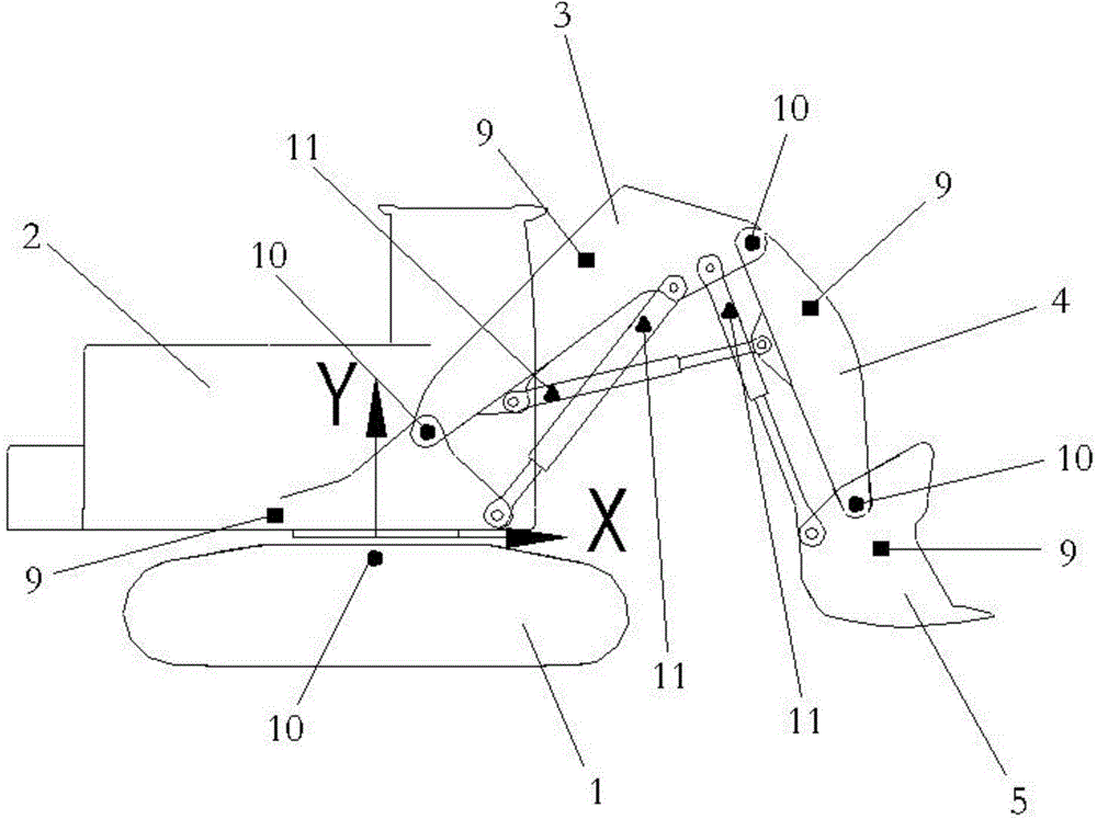
[0025] In this embodiment, the angle sensor 10 is used as a tool for detecting the attitude of the working device, that is, on the slewing bearing 12 of the excavator, the hinge of the upper vehicle 2 and the boom 3, the hinge of the boom 3 and the arm 4, the bucket An angle sensor 10 is installed at the joint between the rod 4 and the bucket 5 .
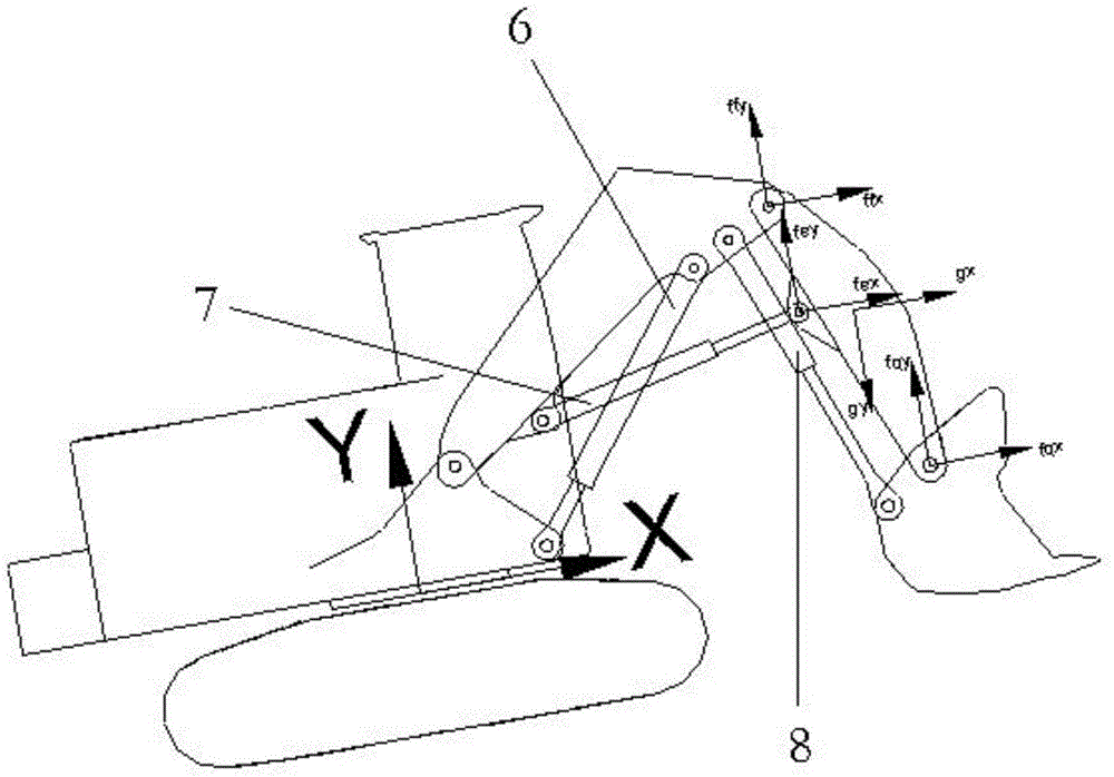
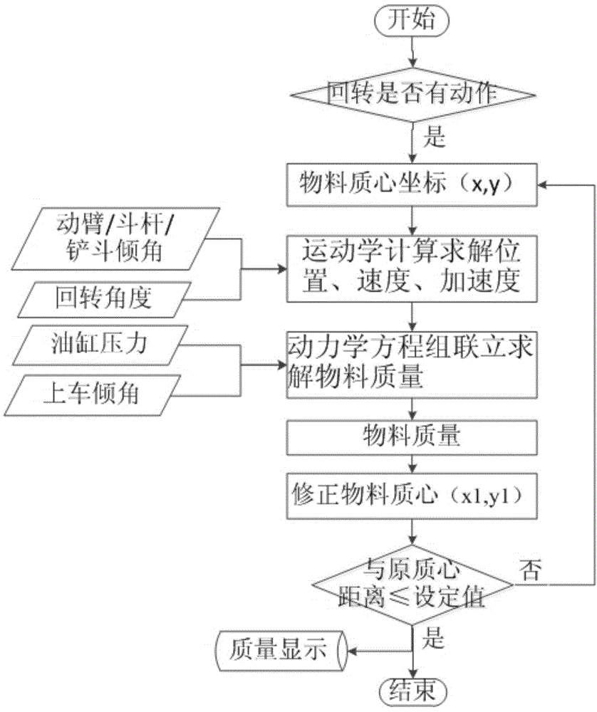
[0026] Please combine Figure 1 to Figure 3 As shown, a method for automatically weighing materials of a mining excavator in this embodiment includes the following steps:
[0027] Step 1: With the center of rotation of the slewing support 12 as the origin, a rectangular coordinate system is established. The coordinate system is fixed on the X-axis direction of the upper vehicle and points horizontally to the direction of the working device, and the Y-axis direction is the vertical upward direction with the center of rotation as the origin. The building coordinate system is fixed on the upper vehicle. Set the coordinates (x, y) of ...
Embodiment 2
[0039] Please continue to see figure 1 As shown, in this embodiment, the inclination sensor 9 is used as a tool for attitude detection of the working device, that is, the inclination sensor 9 is installed on the excavator upper vehicle 2, the boom 3, the arm 4 and the bucket 5. Its material automatic weighing method is basically the same as embodiment one, the difference is that step 2 is modified to:
[0040] Step 2: The main engine calculates the absolute angle between the boom 3, arm 4 and bucket 5 and the horizontal plane through the inclination sensor 9, and then calculates the real-time position, speed, acceleration and other motion state parameters of each component through kinematic differentiation.
[0041] It can also achieve the same technical effect as that of the first embodiment, and its implementation mode is the same as that of the first embodiment, which will not be repeated here.
Embodiment 3
[0043] Please continue to see figure 1 As shown, in this embodiment, the displacement sensor is used as a tool for attitude detection of the working device, that is, the displacement sensor 11 is installed on the arm cylinder 6 , arm cylinder 7 and bucket cylinder 8 of the excavator. Its material automatic weighing method is basically the same as embodiment one, the difference is that step 2 is modified to:
[0044]Step 2: The host calculates the elongation of the boom cylinder 6, arm cylinder 7 and bucket cylinder 8 through the displacement sensor 11, and then calculates the real-time position, speed, acceleration and other motion state parameters of each component through kinematic differentiation.
[0045] It can also achieve the same technical effect as that of the first embodiment, and its implementation mode is the same as that of the first embodiment, which will not be repeated here.
PUM
 Abstract
Description
Claims
Application Information
 - R&D
- Intellectual Property
- Life Sciences
- Materials
- Tech Scout
- Unparalleled Data Quality
- Higher Quality Content
- 60% Fewer Hallucinations
Browse by: Latest US Patents, China's latest patents, Technical Efficacy Thesaurus, Application Domain, Technology Topic, Popular Technical Reports.
© 2025 PatSnap. All rights reserved.Legal|Privacy policy|Modern Slavery Act Transparency Statement|Sitemap|About US| Contact US: help@patsnap.com


