
A new type of limit support

A position-limiting support and position-limiting technology, applied in the direction of pipeline supports, pipes/pipe joints/pipe fittings, mechanical equipment, etc., can solve the problems of large vertical displacement of pipelines, inability to rotate freely, and obstruction of pipeline expansion, etc., to achieve Reduce enterprise costs, facilitate processing, and reduce the effect of limit pipe clamps

Active Publication Date: 2017-02-01
江苏福泰电力设备有限公司
View PDF7 Cites 0 Cited by
  • Summary
  • Abstract
  • Description
  • Claims
  • Application Information

AI Technical Summary

Problems solved by technology

This limit device has some disadvantages: because the limit pipe clamp and the limit support are in surface contact, the pipe cannot rotate freely around the center line of the pipeline; the contact area between the limit pipe clamp and the limit support is relatively large, and the During free expansion, the contact surface will generate a large frictional force, and sometimes this frictional force will hinder the expansion of the pipeline; since the newly installed units in China are all ultra-supercritical units, the vertical displacement of the pipeline is very large, according to the original limit The support can no longer meet the requirements

Method used


Image

  • A new type of limit support
  • A new type of limit support

Examples


Embodiment

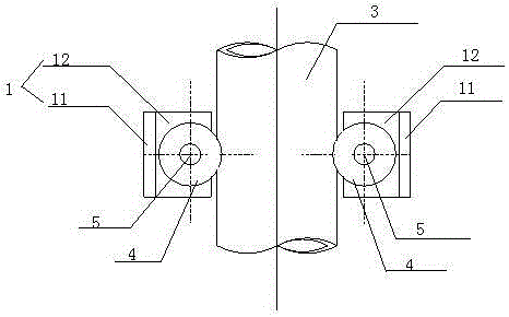
[0012] As shown in the figure, a new type of limit support, which includes two limit support plates 1, the limit support plate 1 is an "n" structure, including a main support plate 11 and two positioning plates 12 , the limit support plate 1 is an integrated structure, the main support plate 11 and the positioning plate 12 are connected by welding; the positioning plate 12 is vertically arranged at both ends of the main support plate 11, and the limit support plate 12 It is arranged on both sides of the pipeline 3, and it is arranged symmetrically with the pipeline 3 as the center; a roller 4 is arranged between the two positioning plates 12 on the said limiting support plate 1, and the two ends of the said roller 4 are tapered surfaces, with the position limiting support The top view of the seat is the reference plane, and the middle part of the roller 4 forms a positioning groove 41, which is a triangular structure. The roller 4 is longitudinally provided with a bearing 5, an...


PUM


Abstract

The invention discloses a novel limiting support. The novel limiting support comprises two limiting supporting plates of an n-shaped structure. Each limiting supporting plate comprises a main supporting plate and two positioning plates, wherein the limiting supporting plate is of an integrated structure, the main supporting plate is connected with the positioning plates in a welded mode, and the positioning plates are perpendicular to the two ends of the main supporting plate. The limiting supporting plates are arranged on the two sides of a pipeline and symmetrically arranged with the pipeline as the center. A wheel is arranged between the two positioning plates of each limiting supporting plate, wherein the two ends of the wheel are provided with taper faces, the top view of the limiting support serves as a reference surface, a positioning groove is formed in the middle of the wheel and is of a triangular structure, a bearing is longitudinally arranged in the wheel, and the two ends of the bearing are fixedly connected to the two positioning plates respectively. By means of the support, the pipeline can be limited in the radial direction and can freely rotate and freely expand in the vertical direction, and the support is simple in structure and convenient to use.

Description

technical field [0001] The invention relates to a position-limiting support. Background technique [0002] During the use of the support and hanger, the limit device occupies a large part. It serves the purpose of restricting and restricting the free displacement of the pipe system caused by thermal expansion in the pipeline support. It is a key product of the support and hanger. Usually the limit support is used in conjunction with the limit pipe clamp. As a commonly used supporting component, the limit device is widely used in the installation of pipelines in nuclear power, thermal power, petrochemical, metallurgical and other industries. [0003] Traditional limit devices include limit pipe clamps, limit supports, steel beams and other components. When in use, the limit support is installed on the outside of the limit pipe clamp, while the contact between the traditional limit pipe clamp and the limit support is surface contact. This limit device has some disadvantages...

Claims


Application Information

Patent Timeline
Patent Type & Authority Patents(China)
IPC IPC(8): F16L3/16
CPCF16L3/202
Inventor 黄喜福
Owner 江苏福泰电力设备有限公司
Learn More