
Universal wheel

A universal wheel and bearing technology, applied in the field of universal wheels, can solve the problems of poor bearing capacity, poor bearing protection and easy to be stained and damaged, and achieve the effect of convenient release of orientation and braking, stable orientation and braking, and firm connection

Active Publication Date: 2016-05-25
宁波科盛万向轮有限公司
View PDF6 Cites 1 Cited by
  • Summary
  • Abstract
  • Description
  • Claims
  • Application Information

AI Technical Summary

Problems solved by technology

[0003] The purpose of the present invention is to overcome the disadvantages of poor bearing capacity and poor bearing protection and easy to be damaged by pollution in the current universal wheel, and provide a universal wheel with better bearing capacity and better bearing protection, which is not easy to be damaged by pollution

Method used


Image

  • Universal wheel
  • Universal wheel
  • Universal wheel

Examples


Embodiment 1

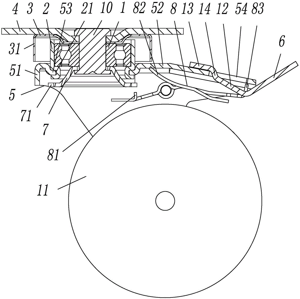
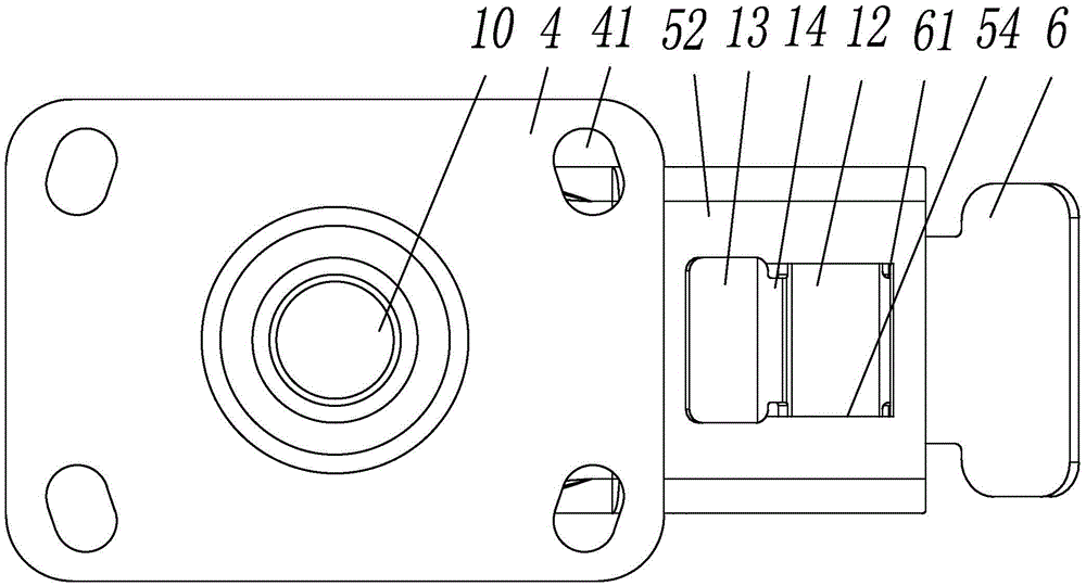
[0021] Embodiment 1, as attached figure 1 , attached image 3 , attached Figure 4 , attached Figure 5 Shown: a universal wheel, including a bearing 1, a bearing seat 2 that covers the outer circumference of the bearing 1 and supports the lower end of the outer ring of the bearing 1, presses the upper end of the inner ring of the bearing 1 and is provided with a side on the outer side of the bearing seat 2 The dustproof cover 3 of the ring 31, press the dustproof cover 3 and the installation plate 4 with four installation holes 41, press the lower steel bowl 7 at the lower end of the inner ring of the bearing 1, pass through the installation plate 4, the dustproof cover 3 1. The fixed rivet 10 of the inner hole of the bearing 1 and the lower steel bowl 7 is provided with two side plates 51 and the prongs 5 ​​of the top plate 52 sleeved outside the bearing seat 2 and connected with the bearing seat 2, and the two side plates 51 The pivoted roller 11 and the locking device; ...

Embodiment 2

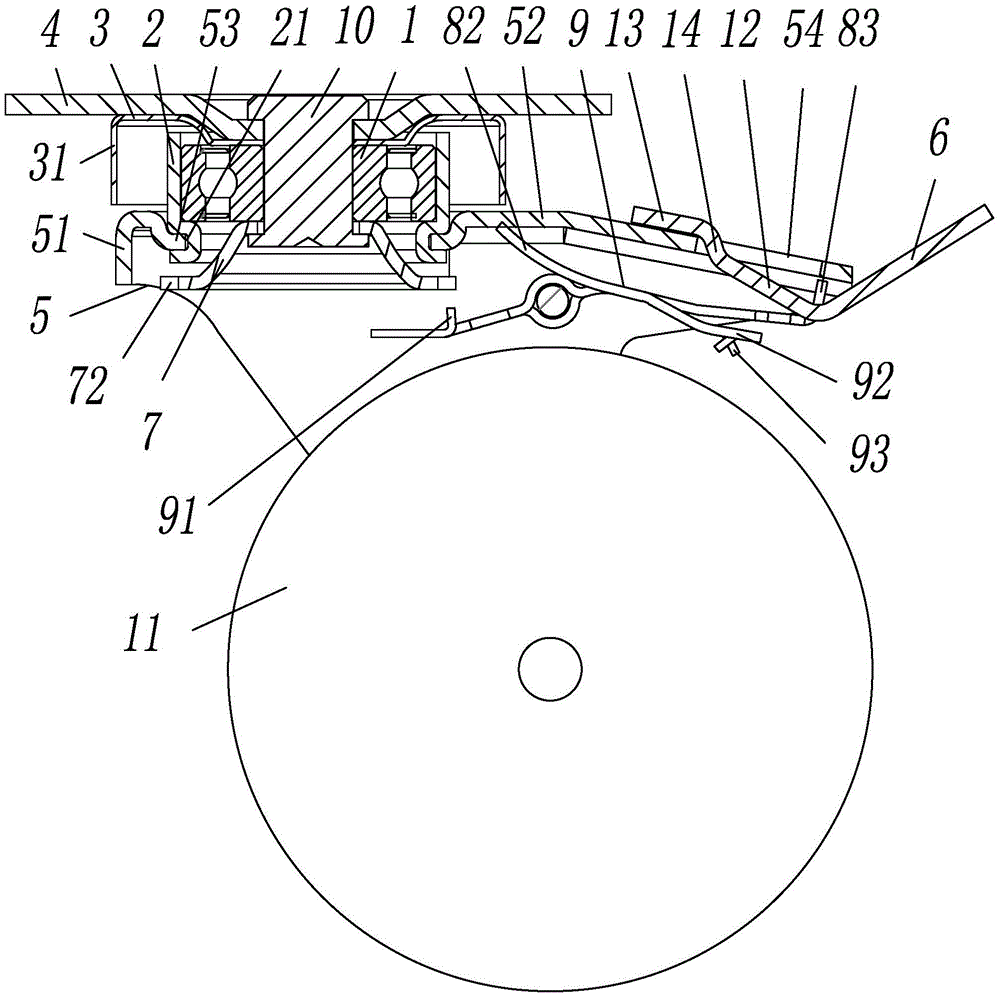
[0024] Embodiment 2, as attached figure 2 , attached image 3 , attached Image 6 , attached Figure 7 Shown: a universal wheel, including a bearing 1, a bearing seat 2 that covers the outer circumference of the bearing 1 and supports the lower end of the outer ring of the bearing 1, presses the upper end of the inner ring of the bearing 1 and is provided with a side on the outer side of the bearing seat 2 The dustproof cover 3 of the ring 31, press the dustproof cover 3 and the installation plate 4 with four installation holes 41, press the lower steel bowl 7 at the lower end of the inner ring of the bearing 1, pass through the installation plate 4, the dustproof cover 3 1. The fixed rivet 10 of the inner hole of the bearing 1 and the lower steel bowl 7 is provided with two side plates 51 and the prongs 5 ​​of the top plate 52 sleeved outside the bearing seat 2 and connected with the bearing seat 2, and the two side plates 51 The pivoted roller 11 and the braking device; ...


PUM


Abstract

The invention relates to the field of trundles, and provides a universal wheel. The universal wheel comprises a bearing, a bearing pedestal, a dust cover, a mounting plate, a lower steel bowl, a fixing rivet, a fork foot and a rolling wheel. The bearing pedestal coats the outer side wall of the bearing and supports the lower end of an outer ring of the bearing. The dust cover presses the upper end of an inner ring of the bearing and is provided with a side ring which is placed on the outer side of the bearing pedestal. The mounting plate presses the dust cover and is provided with a plurality of mounting holes. The lower steel bowl presses the lower end of the inner ring of the bearing. The fixing rivet penetrates through the mounting plate, the dust cover, a bearing inner hole and the lower steel bowl. The fork foot is provided with two side plates and a top plate which is arranged outside the bearing pedestal in a sleeved mode and is connected with the bearing pedestal. The rolling wheel is connected with the two side plates in a pivoted mode. The bearing of the universal wheel is placed among the bearing pedestal, the lower steel bowl and the dust cover and can be protected by the side ring of the dust cover, the bearing capacity of the universal wheel is good, bearing protection is good, and the universal wheel cannot be stained and damaged easily.

Description

technical field [0001] The invention relates to the field of casters, in particular to a universal wheel. Background technique [0002] The utility model of Chinese patent application number: CN200920220173.9 discloses a universal wheel, which includes a wheel seat and a caster. The lower shaft of the caster is provided with a wheel. There is not less than one fixing hole on the back for fixing the wheel base on the luggage; a rivet is fixed at the center of the upper end of the wheel caster, and the rivet is inserted into the bearing to fix the wheel base and the caster together. The universal wheel has the disadvantages of poor load-carrying capacity and poor bearing protection, which is easy to be damaged by pollution; therefore, it is an urgent problem to design a universal wheel with better load-carrying capacity and better bearing protection, which is not easy to be damaged by pollution. Contents of the invention [0003] The purpose of the present invention is to o...

Claims


Application Information

Patent Timeline
Patent Type & Authority Patents(China)
IPC IPC(8): B60B33/00B60B33/02
Inventor 杨华科吴技科
Owner 宁波科盛万向轮有限公司
Learn More