
A low noise mixer circuit

A mixer and low-noise technology, applied in the field of low-noise mixer circuits, can solve the problems of noise, constant current source does not provide gain, etc., to achieve the effects of low noise, increase system power consumption, and reduce power consumption

Active Publication Date: 2017-04-05
CHINA ELECTRONIC TECH GRP CORP NO 38 RES INST
View PDF3 Cites 0 Cited by
  • Summary
  • Abstract
  • Description
  • Claims
  • Application Information

AI Technical Summary

Problems solved by technology

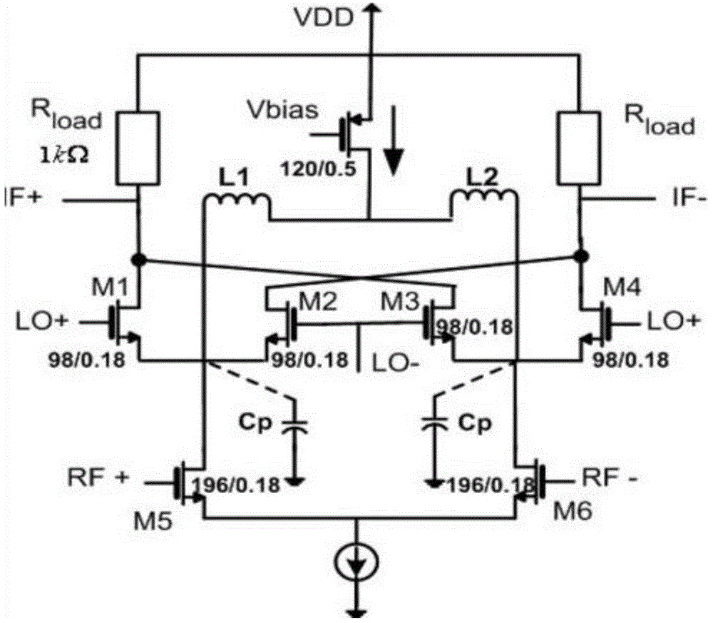
But the consequence of this is that a large parasitic capacitance is introduced at the source of the switching stage, and the constant current source itself does not provide gain but introduces noise

Method used


Image

  • A low noise mixer circuit
  • A low noise mixer circuit
  • A low noise mixer circuit

Examples


Embodiment Construction

[0026] In order to make the object, technical solution and advantages of the present invention clearer, the present invention will be further described in detail below in conjunction with the accompanying drawings and embodiments.

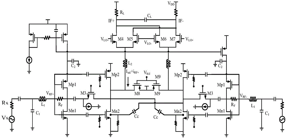
[0027] see image 3 , The low noise mixer circuit of the present invention includes a noise elimination transconductance input stage, a switch mixing stage, and an output load stage.

[0028] The noise canceling transconductance input stage has a differential symmetrical structure, and the structures on the left and right sides are identical. Taking the left side as an example, the structure on the left side includes the first complementary transistor pair Mn1 and Mp1, the second complementary transistor pair Mn2 and Mp2, and the third transistor M3 .

[0029] In the noise elimination transconductance input stage, the gates of the first complementary transistor pair Mn1 and Mp1 are input as a radio frequency differential signal, and the radio freq...


PUM


Abstract

The invention discloses a low-noise frequency mixer circuit. The low-noise frequency mixer circuit comprises a noise elimination trans-conductance input stage, a switch mixing stage and an output load stage, wherein the noise elimination trans-conductance input stage receives a RF voltage signal and converts the RF voltage signal into a current signal; the switch mixing stage is controlled through a local oscillator LO to periodically reverse the current signal and convert the frequency into an intermediate frequency from a radio frequency to finish the frequency conversion; the output load stage carries out filter suppression on a high-frequency signal and converts the corresponding intermediate-frequency signal into an output IF voltage signal. The low-noise frequency mixer circuit improves the effective input trans-conductance of the trans-conductance stage through using a cross coupling method at the noise elimination trans-conductance input stage so as to lower the power consumption of the circuit and achieve low noise.

Description

technical field [0001] The invention belongs to the field of radio frequency integrated circuits, in particular to a low-noise mixer circuit. Background technique [0002] With the scaling down of CMOS process feature size and the continuous improvement of circuit technology, more and more high-performance, highly integrated radio frequency chips (RFICs) have emerged, and these chips have been widely used in various standard wireless communication systems. For example, the demand for wireless local area network (LAN), wireless multimedia and home wireless control systems has grown significantly. [0003] The mixer is an important module in the wireless transceiver, which can realize the function of frequency shifting, and its performance determines the performance of the entire transceiver. According to the noise cascading formula, if the receiver's second-stage unit down-conversion mixer has low-noise characteristics, then the first-stage unit low-noise amplifier can be om...

Claims


Application Information

Patent Timeline
Patent Type & Authority Patents(China)
IPC IPC(8): H03D7/16
Inventor 郭本青王慧芬安士全
Owner CHINA ELECTRONIC TECH GRP CORP NO 38 RES INST
Learn More