
a seal lock

A technology of imprinting and locking shell, applied in the field of anti-theft locks, can solve the problems of preventing the desire to buy and the cost of construction, and achieve the effects of low cost, simple production process, and strong anti-technical opening ability.

Inactive Publication Date: 2017-03-22
温州市安德力五金机械有限公司
View PDF9 Cites 0 Cited by
  • Summary
  • Abstract
  • Description
  • Claims
  • Application Information

AI Technical Summary

Problems solved by technology

The anti-theft ability of the anti-theft lock mainly lies in the structure of the lock cylinder. The more complex the structure, the better the ability to prevent technical opening, but the corresponding cost will also increase.
Therefore, the more expensive the anti-theft lock, the better the anti-theft ability, but it is precisely the expensive price that prevents the user's desire to buy, and the price of hundreds or even thousands is often not considered by the user.

Method used


Image

  • a seal lock
  • a seal lock
  • a seal lock

Examples


Embodiment 1

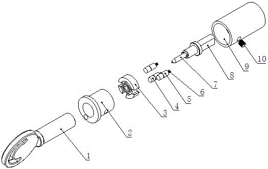
[0030] Embodiment 1: with reference to attached Figure 1-5. An imprint lock, characterized in that it includes a lock case 9, a lock case cover 2, a dial 3, a bolt post 8, an upper lock bead 4, a lower lock bead 5, a compression spring 6, a key 1, and one end of the lock case 9 is provided with a There is a large groove, the lock case cover 2 is packed into the lock case 9 large grooves, the lock case cover 2 and the lock case 9 are fixed with the fixing pin 10, and the dial 3 is placed in the space formed between the lock case cover 2 and the lock case 9 Cavity, number plate 3 two end surfaces are respectively against the bottom surface of lock housing cover 2 and lock housing 9 large grooves; the center of lock housing 9 large grooves has a middle groove, and the center of the middle groove has a through hole, and the lock housing 9 is equipped with Bolt column 8, the bolt column 8 is against the bottom surface of the middle groove, the rotating shaft end of the bolt colum...

Embodiment 2

[0036] Embodiment 2: with reference to attached Figure 6 . An imprint lock, characterized in that it includes a key 1, a lock case cover 2, a dial 3, an upper lock bead 4, a lower lock bead 5, a magnetic bead, a bolt post 8, a lock case 9, and a large groove in the lock case 9 There are 3 small grooves arranged around the bottom surface and the middle groove, and each small groove is equipped with a magnetic bead and a lower lock bead 5. The magnetic bead and the lower lock bead 5 are permanent magnet materials. Repulsive force, the magnetic beads are against the bottom of the small groove. Three through holes are provided on the 3 end faces of the dial, and the positions and numbers of the through holes are

[0037] The amount corresponds to the position and quantity of the lower locking beads 5, and an upper locking bead 4 is placed in each through hole, and the height of the upper locking beads 4 is smaller than the thickness of the dial 3; Enter the through hole of the...

Embodiment 3

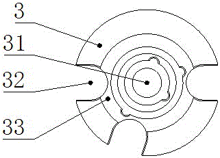
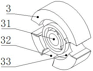
[0038] Embodiment 3: with reference to attached Figure 7 . An imprint lock, which is characterized in that it includes a key 1, a lock case cover 2, a dial 3, an upper lock bead 4, a lower lock bead 5, a compression spring 6, a bolt post 8, and a lock case 9, and the dial 3 is provided with a concave The groove can also be called the key groove 33, and the surface of the key groove 33 faces the end surface of the key and is provided with a combination of protrusions and recesses that cooperate with each other. The protruding part on the surface of the dial key groove is in the shape of an apple pattern, and the key is correspondingly provided with a recess for inserting the protruding part on the surface of the dial key groove.


PUM


Abstract

The invention relates to a novel imprinting lock which comprises a key, a lock shell, a number dial, an upper lock bead, a lower lock bead, a compressed spring, a plug column and a lock shell. A key groove is formed in the number dial, and the key groove face and the key end face are oppositely provided with a convex portion and a concave portion which are mutually matched. A through hole or a gap is formed in the end face of the number dial, the upper lock bead is arranged in the through hole or the gap, the compressed spring and the lower lock bead are arranged in the lock shell, the lower lock bead stretches into the through hole or the gap of the number dial and abuts against the upper lock bead under the action of the compressed spring, and the lower lock bead stops the number dial from rotating. When the key is inserted, if the concave portion in the key end face and the convex portion of the key groove are same in shape, and the inserting portion is correct, the key can be stretched in continuously and ejects the lower lock bead out, and successful unlocking is achieved; if the inserting portion is wrong, the key can just idle. The novel imprinting lock is high in unlocking capacity, the lock core can be protected against violence damage, the production process is simple, the cost is low, the mutual opening rate is low, and individuation making can be achieved.

Description

technical field [0001] The invention relates to an anti-theft lock, which is different from common blade locks and tumbler locks on the market, and is a imprint lock with a new structure. Background technique [0002] Existing mechanical anti-theft locks can be divided into tumbler locks, blade locks, and magnetic locks according to the different lock core principles. [0003] The tumbler lock is the most common lock structure. The principle is that there are several holes radially distributed on the surface of the cylindrical lock core of the marble structure, which correspond to the holes on the lock body and ensure the necessary concentricity. These holes are filled with upper and lower rows of cylindrical pins, that is, upper pins and lower pins. In general, the upper pin in the lock body hole is inserted into the lock cylinder hole, or the lower pin in the lock core is inserted into the lock body hole, so that the lock core cannot be rotated arbitrarily. After the ke...

Claims


Application Information

Patent Timeline
Patent Type & Authority Patents(China)
IPC IPC(8): E05B37/00E05B63/00E05B15/00E05B19/00
Inventor 洪新海李启後
Owner 温州市安德力五金机械有限公司
Learn More