
A device for removing hydrogen in the interlayer of high-vacuum multi-layer heat-insulated tanks by using the waste heat of the tanker

A multi-layer heat insulation and high vacuum technology, applied in other chemical processes, chemical instruments and methods, etc., can solve the problems of reducing the heat insulation performance of the tank, increasing the hydrogen absorption capacity, and energy waste, so as to save time, manpower, and air absorption capacity Large, long-lasting effect

Inactive Publication Date: 2016-03-02
SHANGHAI JIAOTONG UNIV
View PDF2 Cites 0 Cited by
  • Summary
  • Abstract
  • Description
  • Claims
  • Application Information

AI Technical Summary

Problems solved by technology

Although silver oxide has been added to reduce the price to a certain extent, the hydrogen absorption capacity per unit mass of palladium oxide and silver oxide does not increase much. Although the above two hydrogen removal agents work at normal temperature, the hydrogen absorption capacity per unit mass Smaller; while foreign scholars such as H.Londer proposed in "New highcapacitygetterforvacuuminsulatedmobileLH2storagetanksystems" to use barium as the adsorbent and dehydrogenation agent of the interlayer of high vacuum multi-layer thermal insulation storage tanks, which has a large adsorption capacity and is an excellent adsorbent. Barium is very active, rarely exists in nature, hard to get, and requires an activation temperature above 600°C, which is not only a waste of energy, but also reduces the thermal insulation performance of the tank

Method used


Image

  • A device for removing hydrogen in the interlayer of high-vacuum multi-layer heat-insulated tanks by using the waste heat of the tanker
  • A device for removing hydrogen in the interlayer of high-vacuum multi-layer heat-insulated tanks by using the waste heat of the tanker

Examples


Embodiment Construction

[0017] The present invention will be described in detail below in conjunction with specific embodiments. The following examples will help those skilled in the art to further understand the present invention, but do not limit the present invention in any form. It should be noted that those skilled in the art can make several modifications and improvements without departing from the concept of the present invention. These all belong to the protection scope of the present invention.

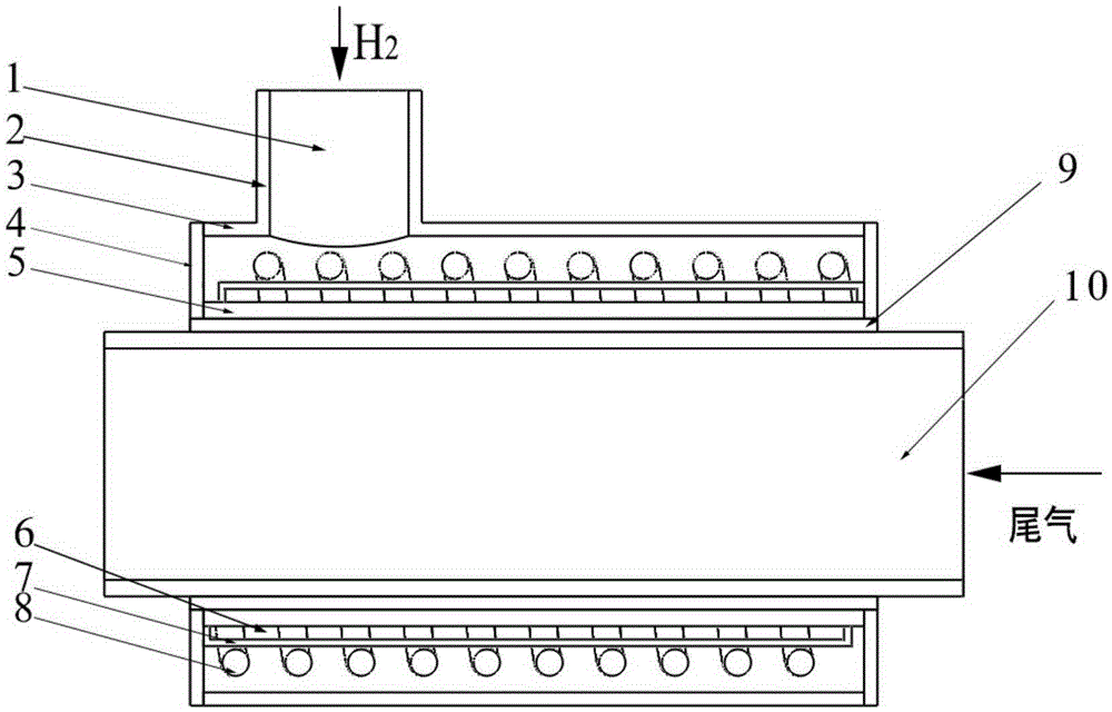
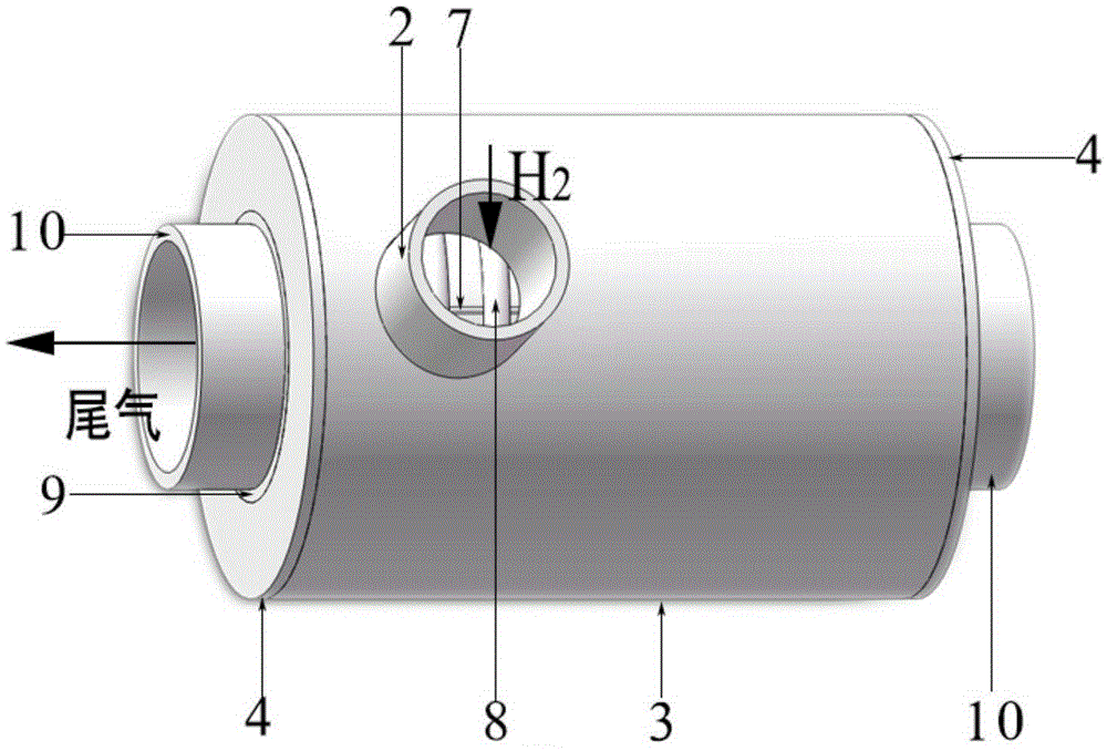
[0018] Such as figure 1 , figure 2 As shown, the present invention includes a sleeve adsorber 1 , a spring bracket 7 , a spring 8 , a heat-conducting silica gel 9 and an exhaust gas pipeline 10 . The casing adsorber 1 includes the casing adsorber inlet 2 , the casing adsorber outer tube 3 , the casing adsorber annular baffle 4 , and the casing adsorber inner tube 5 . The outer tube 3 of the sleeve adsorber and the inner tube 5 of the sleeve adsorber are two concentric metal circular tubes, both...


PUM

PropertyMeasurementUnit
lengthaaaaaaaaaa

Abstract

The invention provides a device of removing hydrogen in a high-vacuum multilayer heat-insulating tank interlayer by utilization of tank car waste heat, and belongs to the technical field of cryogenic engineering and cryogenic technologies. The device comprises a casing adsorber, a spring support, a spring, heat-conducting silica gel and a tail gas pipe. The casing adsorber comprises a casing adsorber gas inlet, a casing adsorber outer pipe, a casing adsorber ring baffle, a casing adsorber inner pipe. During running of a tank car, a tank interlayer generates hydrogen, and the hydrogen enters the casing adsorber through a metal hose and is adsorbed by a composite hydrogen removing agent heated by the tail gas pipe, and therefore the tank interlayer is in a high-vacuum state for a long time. The device is not needed to be disposed inside the tank interlayer, and is communicated with the tank interlayer and the casing adsorber through the metal hose. The device can effectively remove the hydrogen in the interlayer to maintain the vacuum of the interlayer, and has characteristics of low cost, convenient installation and maintenance, and long service lifetime. The composite hydrogen removing agent has advantages of low price and large gas adsorption amount.

Description

technical field [0001] The invention relates to a device for removing hydrogen in the interlayer of a high-vacuum multi-layer heat-insulating tank, in particular to a device for removing hydrogen in the interlayer of a high-vacuum multi-layer heat-insulating tank by using the residual heat of a tanker to heat a composite hydrogen removal agent, belonging to Cryogenic engineering and cryogenic technology. Background technique [0002] At present, tank trucks are an important means of transportation for land transportation of cryogenic liquids, and tanks mainly adopt high-vacuum multi-layer insulation. However, due to the degassing of the interlayer material and the leakage of the tank, the vacuum degree of the interlayer will drop. When the vacuum degree of the interlayer is lower than l×l0 -2 Pa, the thermal insulation effect drops significantly. Studies have shown that metal materials and multi-layer insulation materials of low-temperature pressure vessels, in an environm...

Claims


Application Information

Patent Timeline
Patent Type & Authority Patents(China)
IPC IPC(8): B01D53/04B01J20/06
Inventor 王健汪荣顺
Owner SHANGHAI JIAOTONG UNIV
Learn More