
A radio frequency power amplifier

A radio frequency power and amplifier technology, applied in the field of radio frequency power amplifiers, can solve problems such as loss of function of the load circuit

Active Publication Date: 2018-05-29
ANYKA (GUANGZHOU) MICROELECTRONICS TECH CO LTD
View PDF7 Cites 0 Cited by
  • Summary
  • Abstract
  • Description
  • Claims
  • Application Information

AI Technical Summary

Problems solved by technology

However, in high-frequency circuits, the load circuit of the RF power amplifier is usually an inductance. The inductance has a large area and resonates at a fixed resonance frequency. At this time, after the inductance is adjusted to change the inductance value, the resonance frequency will also change. Make the load circuit not work at the fixed resonant frequency, so that the load circuit loses its own function

Method used


Image

  • A radio frequency power amplifier
  • A radio frequency power amplifier
  • A radio frequency power amplifier

Examples


Embodiment Construction

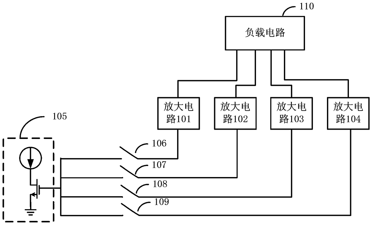
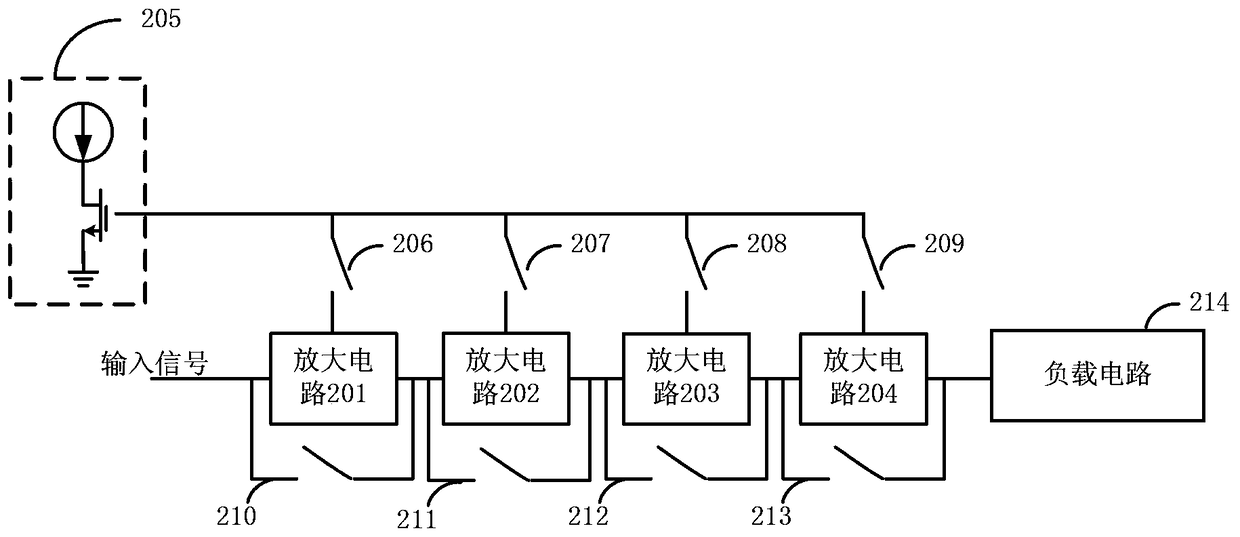
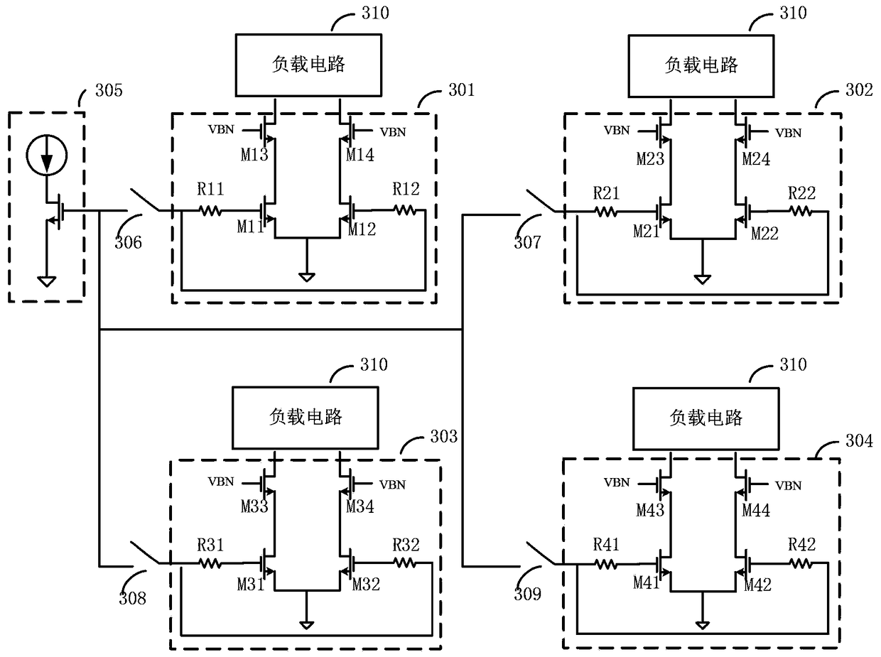
[0025] The present invention provides a specific embodiment of a radio frequency power amplifier. In this embodiment, the amplifier includes: at least two amplifying circuits, at least one bias circuit, and at least one switching device.

[0026] Each of the amplifying circuits is connected in series and / or in parallel. Specifically, all amplifying circuits can be connected in parallel or all can be connected in series, or part of the amplifying circuits in each amplifying circuit can be connected in series, and the amplifying circuits connected in series can be connected in parallel with other amplifying circuits except this part of amplifying circuits, etc. Realization of the present invention. Any amplifying circuit can amplify the signal input to the amplifying circuit, specifically, the amplifying circuit can be composed of one or more amplifying tubes.

[0027] The input signal of the radio frequency power amplifier is output to the load circuit after passing through th...


PUM


Abstract

The present invention provides a radio frequency power amplifier. The amplifier includes: at least two amplifying circuits, at least one bias circuit, and at least one switching device; each of the amplifying circuits is connected in series and / or in parallel; The two amplifying circuits are then output to the load circuit; the at least one bias circuit is used to provide bias current to the at least two amplifying circuits; each switching device is used to control each amplifying circuit to be in two states of working or disconnecting; The amplifier circuit connected to the amplifier in series is also connected with a switch circuit in parallel; the amplifier also includes the switch circuit. It can be seen that by controlling the number of the amplifier circuits in the working state, the gain of the radio frequency power amplifier provided by the present invention can be controlled, and the inductance value of the load circuit will not be adjusted at the same time, so that the resonant frequency of the load circuit will not be changed to ensure the load The circuit resonates at a fixed resonant frequency.

Description

technical field [0001] The invention relates to the field of wireless communication, in particular to a radio frequency power amplifier. Background technique [0002] RF power amplifiers are mainly used in wireless communication systems and are an important part of various wireless transmitters. The RF power amplifier amplifies the input signal and outputs it to the load circuit. In this process, it is usually necessary to control the gain of the radio frequency power amplifier. [0003] In the prior art, the gain of the power amplifier is usually controlled by adjusting the load circuit. However, in high-frequency circuits, the load circuit of the RF power amplifier is usually an inductance. The inductance has a large area and resonates at a fixed resonance frequency. At this time, after the inductance is adjusted to change the inductance value, the resonance frequency will also change. The load circuit does not work at the fixed resonant frequency, so that the load circ...

Claims


Application Information

Patent Timeline
Patent Type & Authority Patents(China)
IPC IPC(8): H03F3/189
Inventor 陈志坚胡胜发
Owner ANYKA (GUANGZHOU) MICROELECTRONICS TECH CO LTD
Learn More