Air dryer suitable for use in dusty environment

An air dryer and environmental technology, applied in applications, refrigerators, household heating and other directions, can solve the problems of large baking and drying pollution, large drying energy consumption, increased cost, etc., to improve dehumidification efficiency, ensure effective heat dissipation, Easy to clean effect

Active Publication Date: 2017-09-26
余方强
View PDF8 Cites 0 Cited by
  • Summary
  • Abstract
  • Description
  • Claims
  • Application Information

AI Technical Summary

Problems solved by technology

[0005] (1) Due to the fluctuation of humidity and the unevenness of drying, the quality of building decoration construction is unstable and the quality is not high
[0006] (2) Electric heating and drying consume a lot of energy
[0007] (3), baking and drying pollution is large
[0008] (4), the above several drying methods still have potential safety hazards in terms of electricity use and fire prevention
[0011] At present, in order to solve this dust problem, those skilled in the art are reducing dust by adding medium-efficiency and high-efficiency filters, but this method will greatly increase the cost, and the volume is huge, and it is extremely inconvenient to move on the construction and decoration site

Method used


Image

  • Air dryer suitable for use in dusty environment
  • Air dryer suitable for use in dusty environment
  • Air dryer suitable for use in dusty environment

Examples


Embodiment 1

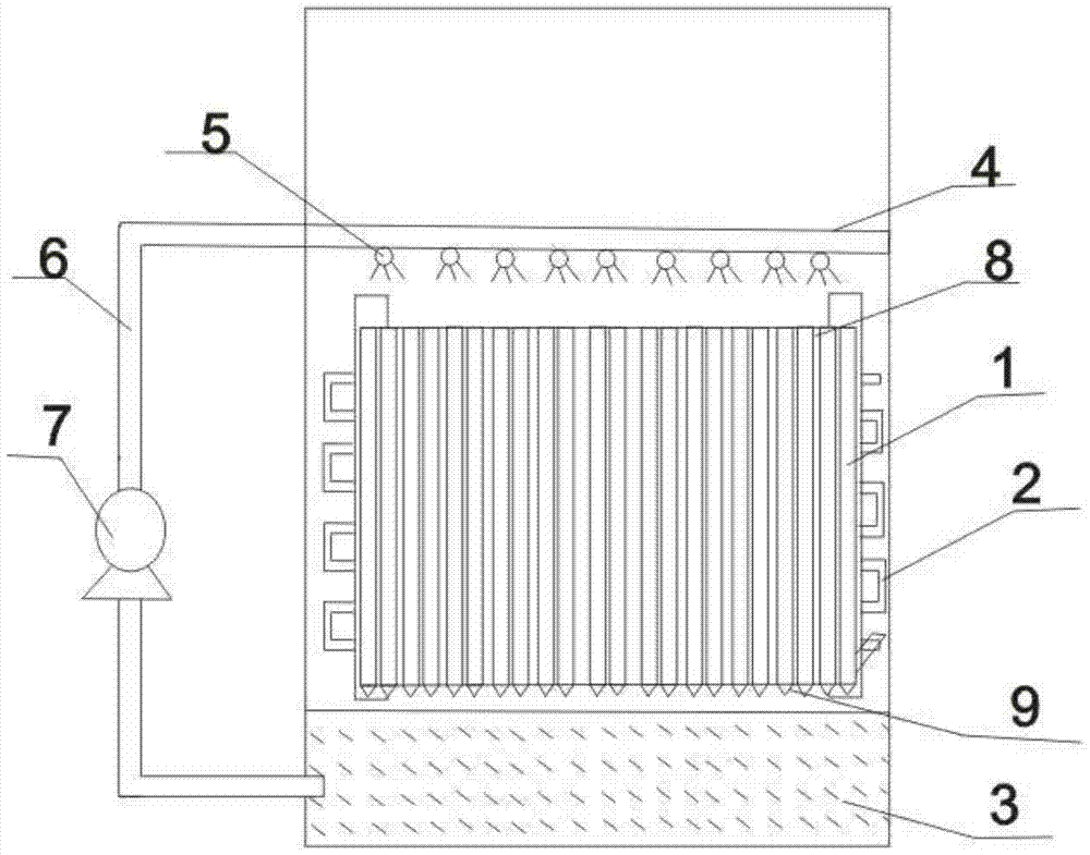
[0041] Example 1, as Figure 1-5 As shown, the air dryer of the present invention suitable for use in a dusty environment includes an evaporator 1 arranged on one side of the air suction port, a condenser 2 arranged side by side with the evaporator 1, and the evaporator 1 and the condenser 2. The water tank 3 below is used to store the condensed water. The air dryer also includes a case, a compressor, a fan, etc., which are the prior art and will not be repeated here. In the present invention, the air inlet is located on the front side of the case, and the air outlet is located in the The position near the rear, this is a conventional design, not shown in the picture.

[0042]Evaporator 1 consists of vertical pipes, the vertical pipes of evaporator 1 are arranged in a spiral, like a horizontally placed columnar spring, and the side of the spiral vertical pipes of evaporator 1 is away from the air intake. A whole piece of heat sink 8 is provided. A triangular drip block 9 is ...

Embodiment 2

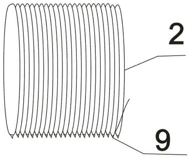
[0046] like Figure 6-8 Shown: other structures are the same as in Example 1, the difference is that the condenser 2 and the evaporator 1 have the same structure, the condenser 2 is also composed of vertical pipes, and the vertical pipes of the condenser 2 are also spiral tight arrangement. Only the pipe diameter of the vertical exhaust pipe of the condenser 2 is smaller than the pipe diameter of the vertical exhaust pipe of the evaporator 1 . A triangular drip block 9 is provided on the tube wall of the bottom end of the vertical pipe of the evaporator 1 . A whole piece of radiating fins 8 is also provided on one side of the spiral vertical pipe of the condenser 2 .

Embodiment 3

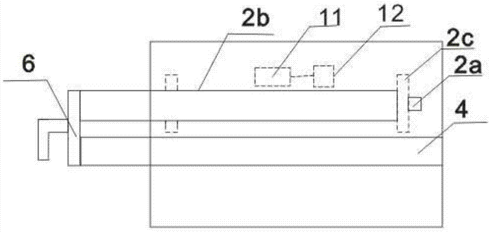
[0048] like Figure 9-10 As shown: other structures are the same as in Embodiment 1, the difference is that the condenser 2 includes mounting plates 2c at both ends, and two rows of transverse coils 2a are arranged between the mounting plates 2c at both ends. The heights of the coils 2a are arranged at different heights.


PUM


Abstract

The invention discloses an air dryer suitable for use in a dusty environment, comprising an evaporator, a condenser arranged side by side with the evaporator, and a water tank located under the evaporator and the condenser, and the evaporator is composed of vertical pipes , the vertical pipes of the evaporator are arranged in a spiral shape, there are water spray pipes above the evaporator and the condenser, nozzles are distributed on the lower side wall of the water spray pipes, and the water inlet of the water spray pipes extends out of the chassis The water pipe is connected, and the water pipe is connected with a pump. The design of the drying machine of the present invention makes it possible for the dehumidifier to be used as an air drying machine in harsh environments such as building construction and decoration. (1) Reduce the drying energy consumption by 50%, improve the drying efficiency of the building construction and decoration industry, (2) make the drying uniform, and ensure the quality of the building construction and decoration, (3) shorten the construction period and improve labor productivity, (4) ) improves the construction environment, and the drying machine of the present invention is used in a building decoration environment, and quality problems will not occur for up to five years.

Description

technical field [0001] The invention relates to an air dryer, in particular to an air dryer suitable for use in building construction. Background technique [0002] At present, ordinary dehumidifiers include a chassis, which forms the appearance of the dehumidifier, and accommodates and protects various components of the dehumidifier; the evaporator is arranged on the side of the air intake. When the air passes through the evaporator, the moisture in the air condenses into condensed water on the evaporator; the condenser is arranged side by side with the evaporator. When the dehumidifier is running, the condenser is in a high temperature state, and the air passing through the evaporator flows through the condenser. During the heat exchange with the condenser, the temperature of the refrigerant in the condenser is lowered, and the temperature of the air is increased at the same time. The drain port leads to the water tank; the fan sucks and exhausts air into the case, so tha...

Claims


Application Information

Patent Timeline
Patent Type & Authority Patents(China)
IPC IPC(8): F24F1/02F24F13/30F24F13/22F25B39/02F25B39/04B01D53/26
Inventor 余方强
Owner 余方强
Why Eureka
Try Eureka