
Crop reaping and binding machine

A technology of a baler and a baling mechanism, which is applied in the direction of balers, harvesters, agricultural machinery and implements, etc., can solve the problems of difficulty in grasping the best harvest timing, increased pod burst loss, and increased operating costs, etc. Achieve the effect of improving the economic benefits of crop production, alleviating the contradiction between the stubble and avoiding the loss of mildew

Inactive Publication Date: 2014-10-15
HUNAN AGRICULTURAL UNIV
View PDF10 Cites 21 Cited by
  • Summary
  • Abstract
  • Description
  • Claims
  • Application Information

AI Technical Summary

Problems solved by technology

[0002] For a long time, crops (such as rapeseed) have had a problem of high loss rate in the harvesting of existing combine harvesters. Poor performance leads to large grain loss in the field; on the other hand, it is difficult for crops to grasp the best harvesting time when harvesting. Premature harvesting will cause low oil content in the seeds, which will affect the yield and quality of harvesting. Overripe harvesting will cause siliques to burst Increased losses, which eventually lead to higher harvest loss rates
The traditional segmental harvesting is to use the windrower to cut the immature crops and spread them in the field to ripen, and then pick them up in the field with a picker and feed them into the thresher for threshing. Although the harvest loss of the crops is reduced, the crops The post-ripening time in the field is generally 3-5 days. If it rains, it may cause the crop seeds to rot and the loss rate will be higher
In addition, the number of operations of work tools in the field increases, and the operating cost increases accordingly.

Method used


Image

  • Crop reaping and binding machine
  • Crop reaping and binding machine
  • Crop reaping and binding machine

Examples


Embodiment Construction

[0021] The present invention will be further described below in conjunction with the accompanying drawings and preferred embodiments.

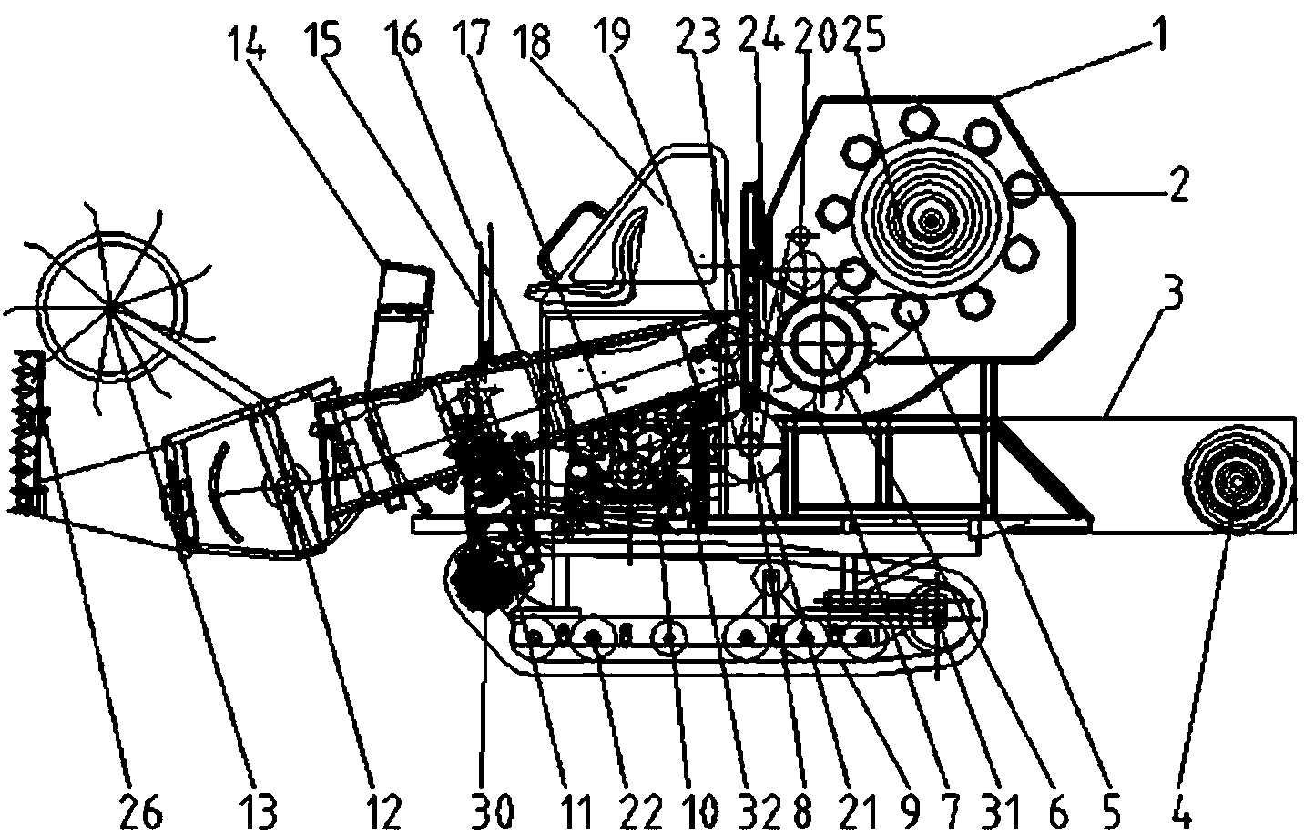
[0022] Such as Figure 1 to Figure 5 As shown, the crawler-type harvesting and bundling machine of the present embodiment is mainly composed of a header 12, a conveying trough, a feeding device, a bundling mechanism 1 and a power walking system and the like.

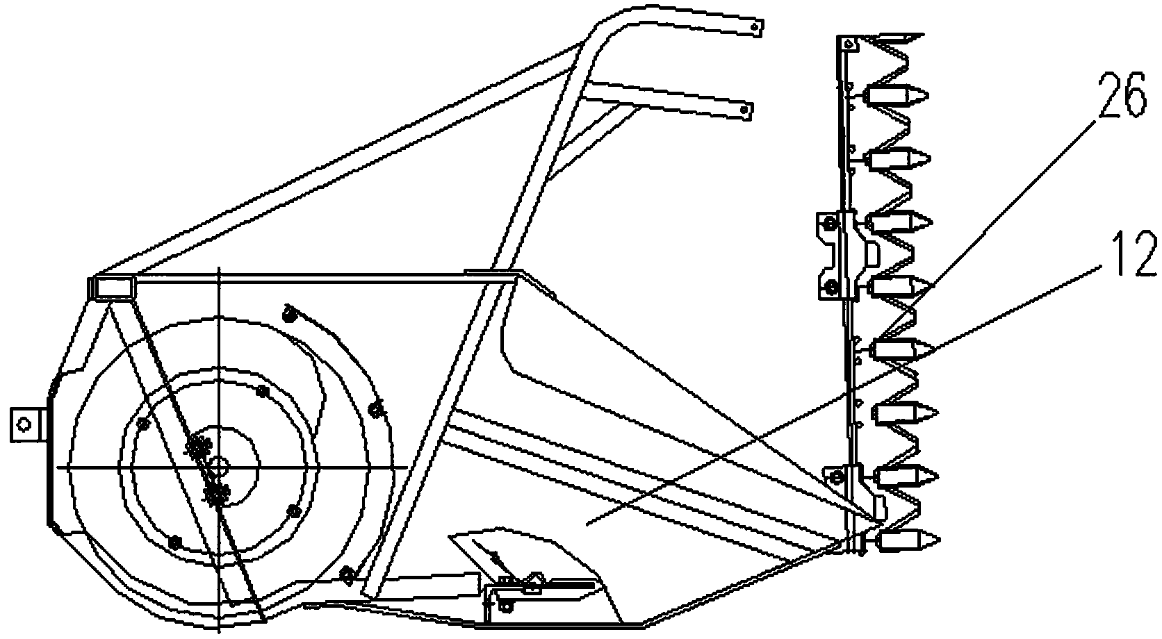
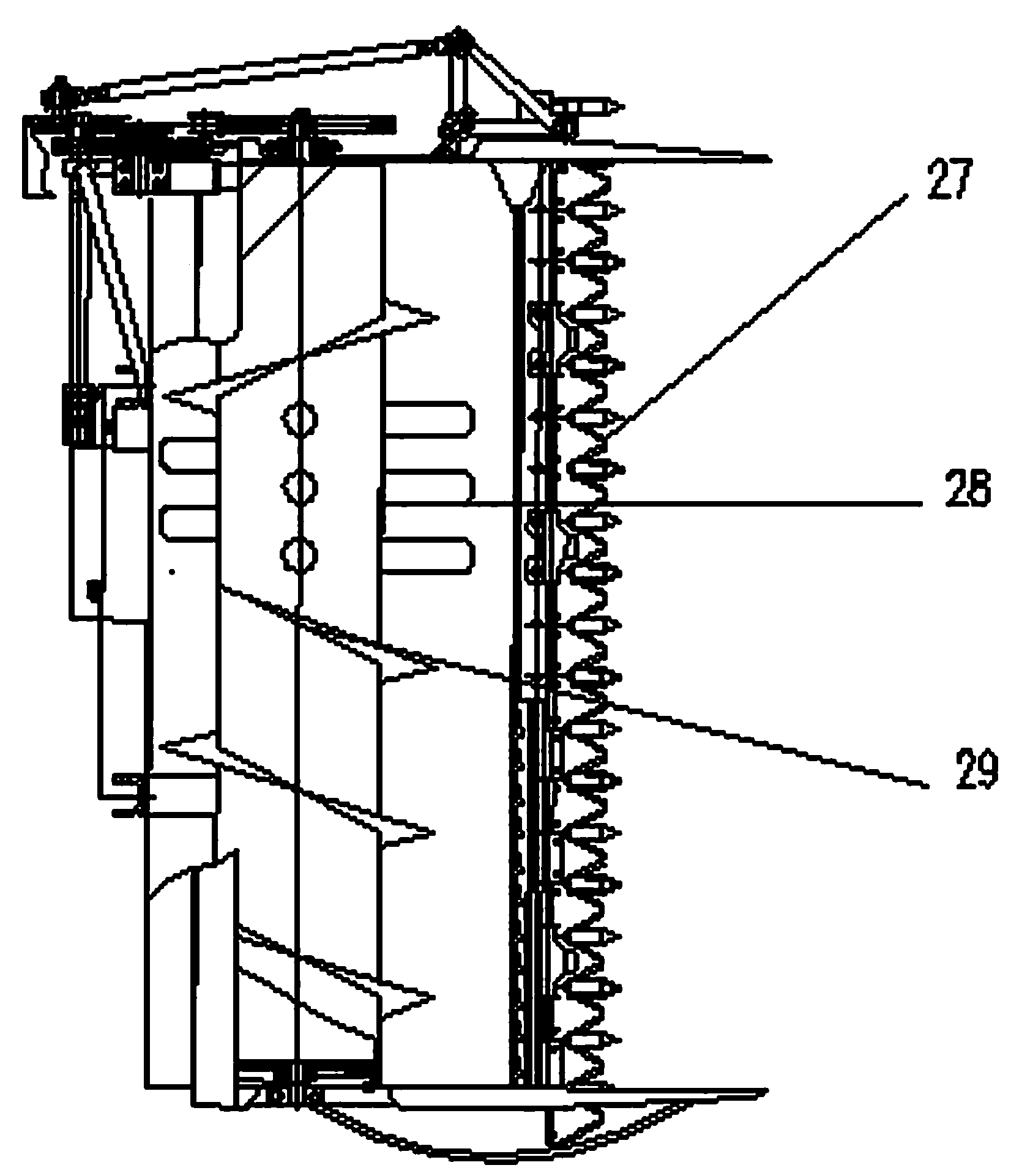
[0023] In this embodiment, the header 12 is mainly composed of a side reciprocating cutter 26, a lateral reciprocating cutter 27, a reel 13, a spiral auger 29 and telescopic teeth 28, and the crops are cut by the side reciprocating cutter 26 Cutting and separating are used to reduce the entanglement and resistance of the crops to the moving equipment. The horizontal reciprocating cutter 27 cuts down the crops, and the reel 13 shifts the crops to the auger 29, and the auger 29 transports the crops Dial to the delivery groove through telescopic grilling teeth 28 to the delivery slot.

[...


PUM


Abstract

The invention discloses a crop reaping and binding machine. The crop reaping and binding machine comprises a reaping table, a conveying groove, a feeding device, a binding mechanism and a dynamic travelling system, wherein the reaping table pulls crops to the conveying groove after reaping the crops, the conveying groove conveys the crops to the feeding device, the feeding device feeds the crops into the binding mechanism, and the binding mechanism binds the crops, bound crops fall into a storage box after being discharged and then are concentratedly transported to an appointed place, and the dynamic travelling system is used for realizing a travelling function of the binding machine and providing power for the conveying groove and the binding mechanism. The crop reaping and binding machine has the advantages that by means of finishing the processes of reaping, picking, binding, storing and the like at a time, a cropland is emptied for next-stubble crops immediately, and crop rotation contradiction is relieved; in addition, the crops are transported to the fixed places for concentrated after-ripening, so that crop seeds are protected from mildewing loss caused by overcast and rainy weather, and the economic benefit for crop production is increased.

Description

technical field [0001] The invention relates to a harvesting and bundling machine for crops, in particular to a harvesting and bundling operation for segmented harvesting of crops, belonging to the technical field of agricultural machinery. Background technique [0002] For a long time, crops (such as rapeseed) have had a problem of high loss rate in the harvesting of existing combine harvesters. Poor performance leads to large grain loss in the field; on the other hand, it is difficult for crops to grasp the best harvesting time when harvesting. Premature harvesting will cause low oil content in the seeds, which will affect the yield and quality of harvesting. Overripe harvesting will cause siliques to burst Loss increases, which eventually leads to a higher harvest loss rate. The traditional segmental harvesting is to use the windrower to cut the immature crops and spread them in the field to ripen, and then pick them up in the field with a picker and feed them into the t...

Claims


Application Information

Patent Timeline
IPC IPC(8): A01D37/00
Inventor 吴明亮吴梓高罗海峰谢方平石增祥王修善
Owner HUNAN AGRICULTURAL UNIV
Learn More