
Novel self-energy type liquid metal current limiter and method

A liquid metal, current limiter technology, applied in electrical components, electrical switches, circuits, etc., can solve the problems of reducing automation level, large loss, long arcing time, etc., to achieve good self-recovery and enhance current limiting ability. , The effect of increasing the arc voltage

Inactive Publication Date: 2014-10-08
XI AN JIAOTONG UNIV
View PDF4 Cites 14 Cited by
  • Summary
  • Abstract
  • Description
  • Claims
  • Application Information

AI Technical Summary

Problems solved by technology

However, the application technology of superconducting materials for high-power applications is still immature and the reliability is poor. At the same time, it takes a long time for superconductors to return to the superconducting state, so it is generally difficult to meet the requirements of automatic reclosing and other aspects, and liquid nitrogen is also required for recovery. And other auxiliary refrigerants and refrigeration equipment, the additional loss is large, etc.
[0006] The current-limiting fuse is currently the only commercialized fault current limiter. The short-circuit current can be forcibly limited before reaching the first peak value by using the rapidity of the fuse. For example, the patent number is 200410025999.1, and the patent name is 'Large capacity short The patented current-limiting fuse of the current breaker completes the breaking of large overload current and short-circuit current, but the fuse is a single action, which reduces the automation level of the system operation. For grids with complex structures, the selectivity of protection is sacrificed

Method used


Image

  • Novel self-energy type liquid metal current limiter and method
  • Novel self-energy type liquid metal current limiter and method
  • Novel self-energy type liquid metal current limiter and method

Examples


Embodiment Construction

[0031] The following examples are used to further describe the present invention in detail.

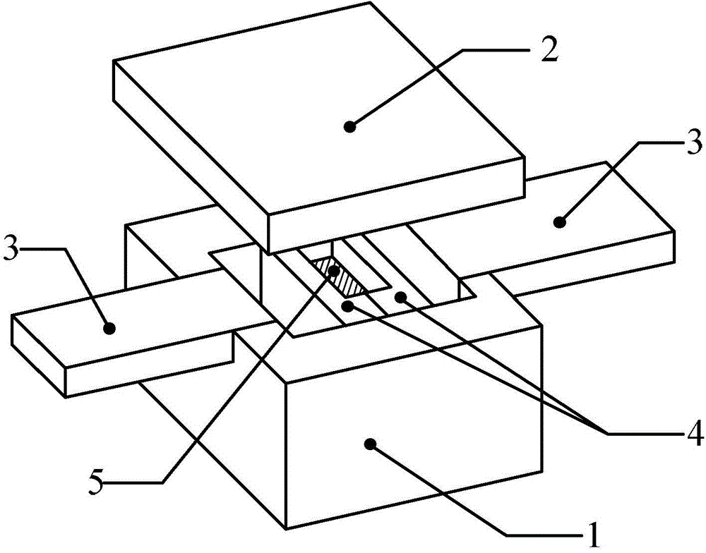
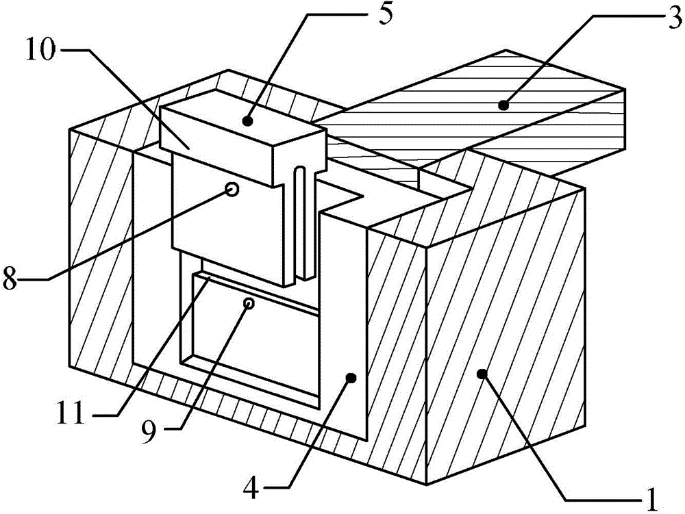
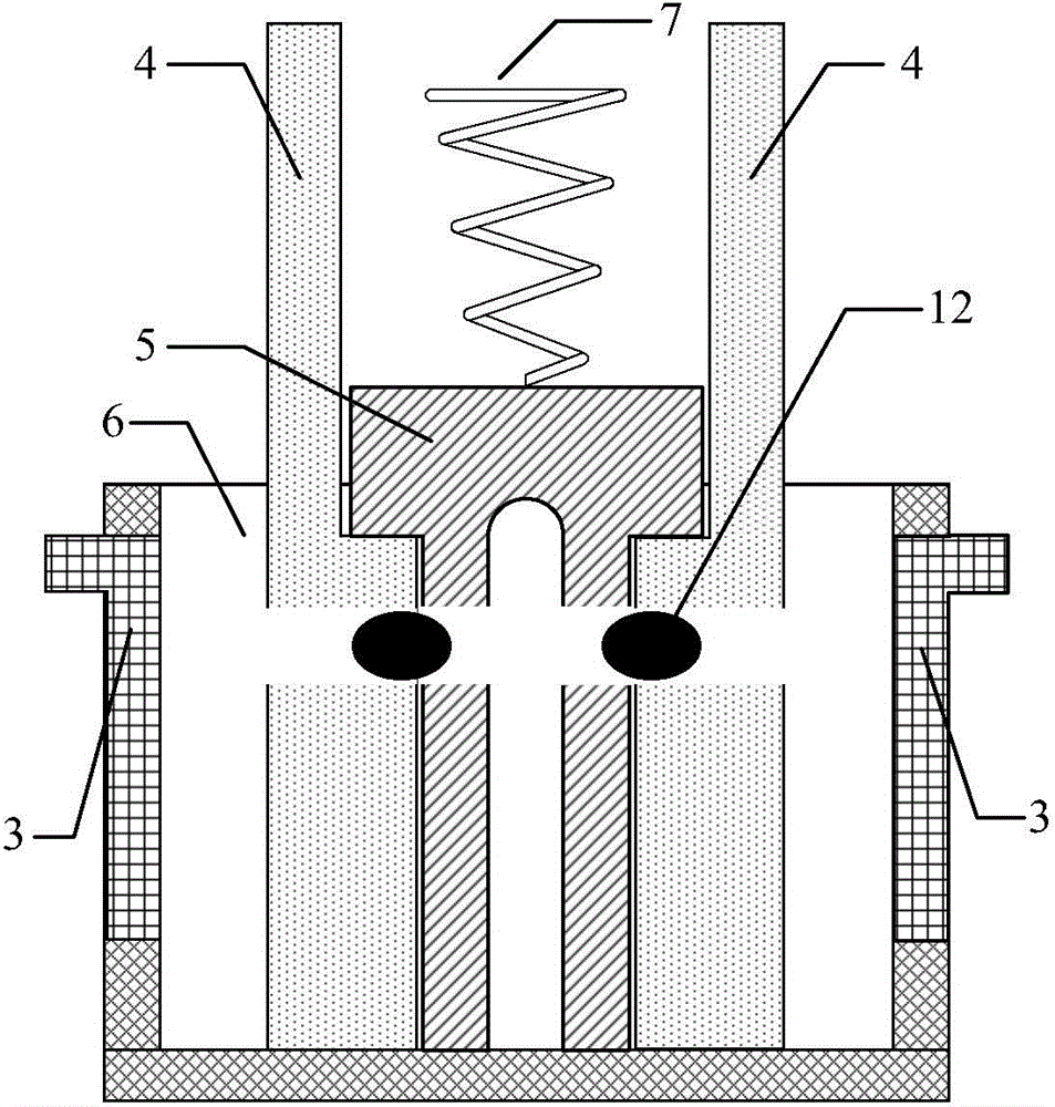
[0032] In one embodiment, the self-energized liquid metal current limiter of the present invention includes at least two insulating baffles (4), on which a flow hole a (9) is arranged on the insulating baffles, and a Movable insulating drawing plate (5), the both sides of the movable insulating drawing plate are provided with flow holes b (9); liquid metal (6) is then submerged in flow holes a (9), flow holes b ( 8), the liquid metal (6) realizes circulation on both sides of the insulating baffle (4) through the flow hole a (9), and the flow hole a (9) and the flow hole b (8) are formed when the system current is normal Stable current channel;

[0033] In the case of normal conduction, the rated current flows through the liquid metal in the through-hole b and through-hole a of the insulating baffle and the movable insulating drawer;

[0034]When a fault occurs, the current limiter u...


PUM


Abstract

The invention provides a novel self-energy type liquid metal current limiter and a current limiting method. The novel self-energy type liquid metal current limiter is characterized in that liquid metal carries out self-constriction arcing under the fault current condition and is gasified under the effect of electric arcs, generated powerful metal steam is continuously accumulated and finally pushes a movable insulation draw plate arranged between insulation baffles to upwards slide, the electric arcs between the insulation baffles and the draw plate are rapidly extruded into a slit and are further lengthened, then the voltage of the electric arcs is rapidly increased, and the fault current is further limited. The novel self-energy type liquid metal current limiter is simple in structure and particularly suitable for limiting the fault current of alternating-direct current systems in the medium-low voltage field, and burdens of various electrical devices such as breakers can be assisted to be relieved.

Description

technical field [0001] The invention relates to electrical switchgear, which is suitable for limiting the fault current of AC and DC systems in the field of medium and low voltages, and in particular relates to a novel self-energy liquid metal current limiter and its method. Background technique [0002] With the increase of power system capacity year by year, the short-circuit capacity and short-circuit current level of the power grid are also increasing, which has become an important problem restricting the operation and development of the power grid. Therefore, research on effective short-circuit current limiting devices to limit the short-circuit capacity of the power system and improve the reliability of the power system has become an urgent issue for the safe and stable operation of the power system and the construction and development of power systems in my country. So far, the technologies applied to short-circuit current limiting mainly include: series current-limit...

Claims


Application Information

Patent Timeline
IPC IPC(8): H01H29/02H01H29/30
Inventor 吴翊何海龙荣命哲杨飞纽春萍李美李阳
Owner XI AN JIAOTONG UNIV
Learn More