Sliding plate valve for dry-mixed mortar storage tank

A dry powder mortar and storage tank technology, applied in the direction of sliding valve, valve details, valve device, etc., can solve the problems of short service life, difficulty in closing the gate, backlog, etc., and achieve the effect of labor-saving, reliable closing or opening.

Inactive Publication Date: 2014-10-08
胡文磊
View PDF7 Cites 3 Cited by
  • Summary
  • Abstract
  • Description
  • Claims
  • Application Information

AI Technical Summary

Problems solved by technology

Because the material in the discharge channel is dry powder mortar powder material, the pressure is high and the density is high. When the ram moves horizontally when it is closed, the ram will backlog the material, making it difficult to close the ram, and the ram bears a huge load. The pressure given by the powdered material of dry powder mortar and the friction between the gate and the valve body are extremely high, which is also one of the reasons for the difficulty in closing the gate.
The above reasons cause the discharge valve of the dry powder mortar storage tank to be difficult to operate, have a high failure rate, and have a short service life.

Method used


Image

  • Sliding plate valve for dry-mixed mortar storage tank
  • Sliding plate valve for dry-mixed mortar storage tank
  • Sliding plate valve for dry-mixed mortar storage tank

Examples


Embodiment 1

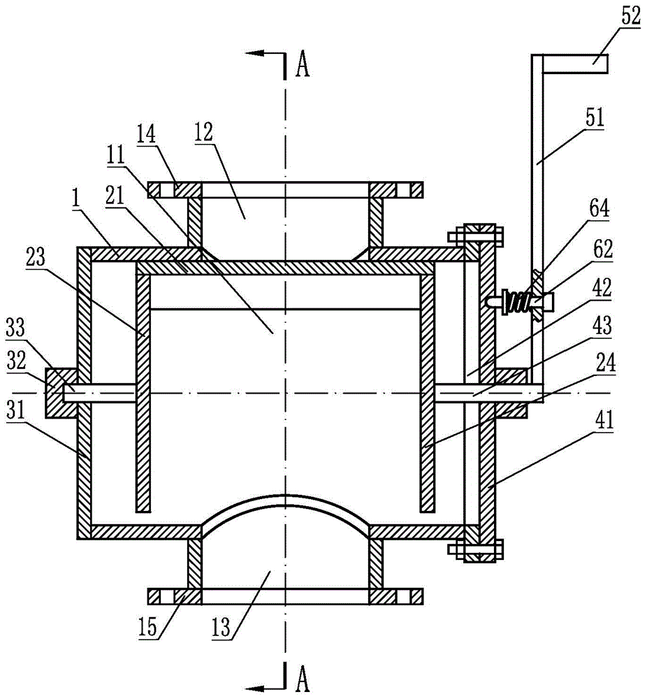
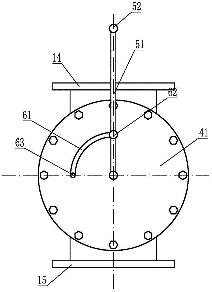
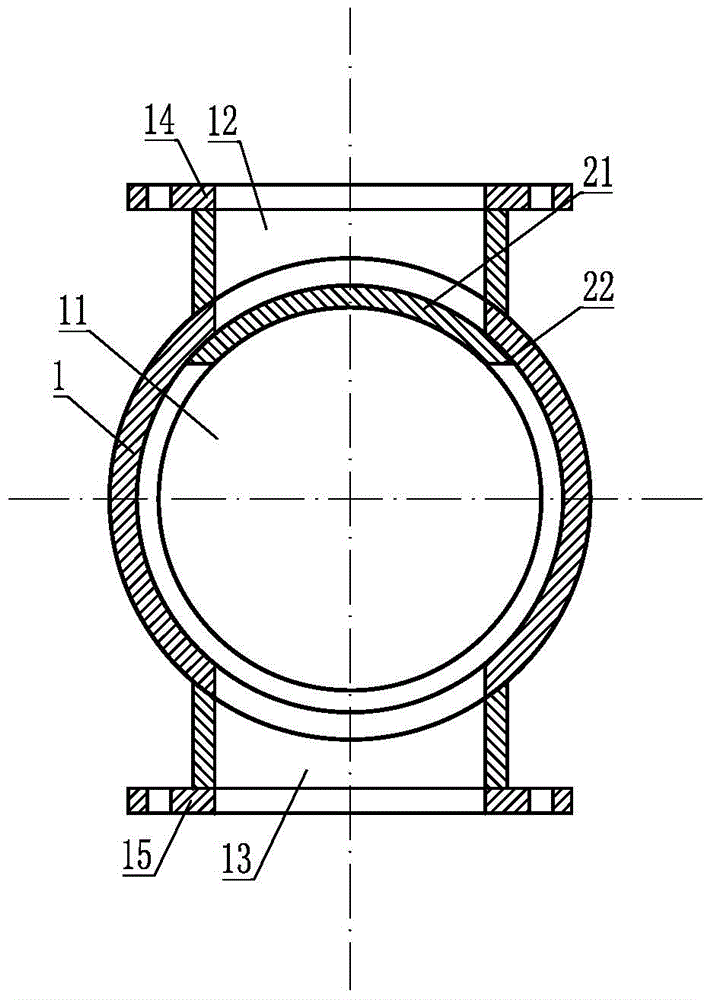
[0023] Such as figure 1 with figure 2 As shown, the slide valve for the dry powder mortar storage tank is installed on the discharge end of the dry powder mortar storage tank, and includes a valve seat 1. The valve seat 1 is provided with a cylindrical valve inner cavity 11, and the valve seat is provided with A feed channel 12 perpendicular to the valve inner cavity 11 and communicated with the valve inner cavity 11, and a discharge channel 12 perpendicular to the valve inner cavity 11 and communicated with the valve inner cavity 11 is provided on the valve seat passage 13, the valve seat is provided with a feed flange 14 and a discharge flange 15; the valve inner chamber 11 is equipped with an arc-shaped rotating slide plate 21 for blocking the feed passage 12, as image 3 with Figure 4 As shown, when the arc-shaped rotating slide plate 21 is closed, the edge of the extruded material is provided with a material cutting edge, such as Figure 5 As shown, when the slide va...

Embodiment 2

[0026] This embodiment is basically the same as Embodiment 1, the difference is: as Image 6 with Figure 7 As shown, when the arc-shaped rotating slide plate 21 is closed, a triangular tip 25 is provided on the edge of the extruded material, and a material cutting edge is provided on the edge of the triangular tip 25 .

[0027] When the slide valve is closed, the triangular tip 25 of the arc-shaped rotating slide plate 21 separates the material to both sides while dividing the material up and down, slowly blocking the feed channel 12, and the triangular tip 25 makes the arc rotate The resistance received by the sliding plate 21 when it rotates and closes is further reduced, so that the closing operation of the sliding plate valve is more labor-saving, and the situation that the arc-shaped rotating sliding plate 21 is stuck will not occur, and the service life of the sliding plate valve can be extended.


PUM


Abstract

The invention discloses a sliding plate valve for a dry-mixed mortar storage tank. The sliding plate valve comprises a valve base, a valve inner cavity is formed in the valve base, a feeding channel and a discharging channel are formed in the valve base, an arc-shaped rotating sliding plate is arranged in the valve inner cavity, a first rotating disc and a second rotating disc are arranged at the two ends of the arc-shaped rotating sliding plate respectively, a first blocking plate and a second blocking plate are arranged at the two ends of the valve inner cavity respectively, a first rotating connecting device is arranged between the first blocking plate and the first rotating disc, a second rotating connecting device is arranged between the second blocking plate and the second rotating disc, the second rotating connecting device is connected with a sliding plate rotating control device, and a rotating limiting locking device is arranged between the sliding plate rotating control device and the second blocking plate. When the valve is used, the sliding plate rotating control device is utilized for rotating the arc-shaped rotating sliding plate, a discharging opening is blocked, the rotating limiting locking device can limit the rotating angle of the sliding plate, an arc-shaped plate is adopted by the sliding plate, force, acting on the sliding plate, of mortar can be dispersed, operation is easy and convenient, and the service life of the sliding plate is prolonged.

Description

technical field [0001] The invention relates to a valve, in particular to a valve suitable for a storage tank of dry powder mortar. Background technique [0002] A gate valve for controlling the switch of the discharge port is installed at the discharge port of the dry powder mortar storage tank. In the prior art, the control valve includes a gate. When discharging, the gate is pulled out. When closed, It is necessary to push the ram into and block the discharge channel. Because the material in the discharge channel is dry powder mortar powder material, the pressure is high and the density is high. When the ram moves horizontally when it is closed, the ram will backlog the material, making it difficult to close the ram, and the ram bears a huge load. The pressure given by the dry powder mortar powder and the friction between the gate and the valve body are extremely high, which is also one of the reasons for the difficulty in closing the gate. The above-mentioned reasons c...

Claims


Application Information

Patent Timeline
Patent Type & Authority Applications(China)
IPC IPC(8): F16K3/02F16K3/30
CPCB65D90/54F16K3/22F16K3/314F16K31/602
Inventor 胡文磊张俊利
Owner 胡文磊
Why Eureka
Try Eureka