
An electronic device and projection display method

A technology for electronic equipment and projection display, which can be used in instruments, printing devices, mechanical mode conversion, etc., and can solve problems such as inconvenience for users to use

Active Publication Date: 2018-04-27
LENOVO (BEIJING) LTD
View PDF6 Cites 0 Cited by
  • Summary
  • Abstract
  • Description
  • Claims
  • Application Information

AI Technical Summary

Problems solved by technology

The mobile terminal in the prior art can only realize the function of projecting the content displayed on the terminal onto the plane, and the operations on the displayed content are all performed on the screen of the terminal, so that the user's line of sight needs to switch repeatedly between the terminal screen and the projection plane , it is not convenient for users to apply
In the prior art, there is no method and device that enables the user to operate the projected content on the projected plane to control the terminal

Method used


Image

  • An electronic device and projection display method
  • An electronic device and projection display method
  • An electronic device and projection display method

Examples


Embodiment Construction

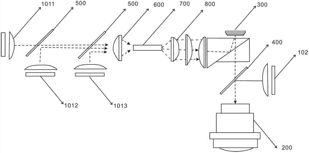
[0064] In order to solve the above-mentioned technical problems, an embodiment of the present invention provides an electronic device and a projection display method, which can conveniently determine the position of a projection area, thereby improving recognition accuracy.

[0065] In order to enable those skilled in the art to better understand the technical solutions in the present invention, the technical solutions in the embodiments of the present invention will be clearly and completely described below in conjunction with the drawings in the embodiments of the present invention. Obviously, the described The embodiments are only some of the embodiments of the present invention, not all of them. Based on the embodiments of the present invention, all other embodiments obtained by persons of ordinary skill in the art without making creative efforts shall fall within the protection scope of the present invention.

[0066] see figure 1 , is a schematic diagram of the first em...


PUM


Abstract

An embodiment of the present invention provides an electronic device and a projection display method using the electronic device, the electronic device includes a light source and a lens, wherein the light source includes at least one visible light source and at least one infrared light source , the at least one visible light source is used to emit visible light, and the at least one infrared light source is used to emit infrared light; the lens is used to project the mixed visible light and the infrared light emitted by the infrared light source to project and display the first projected image in the projected area; wherein, the projected area corresponding to each pixel of the first projected image is incident by visible light and infrared light. Since the projection area corresponding to each pixel of the projection image transmitted by the electronic device provided by the present invention has visible light and infrared light incident, it is convenient to determine the position of the projection area through the infrared light reflected in the projection area, and then accurately perform Gesture Recognition.

Description

technical field [0001] The invention relates to the field of electronic equipment, in particular to an electronic equipment and a projection display method. Background technique [0002] The current mobile terminal has integrated a projection module and has a projection function. The projection module of the mobile terminal can be used to project the content displayed on the terminal on a plane, such as a wall or a desktop, so that the user can obtain a larger image display. The mobile terminal in the prior art can only realize the function of projecting the content displayed on the terminal onto the plane, and the operations on the displayed content are all performed on the screen of the terminal, so that the user's line of sight needs to switch repeatedly between the terminal screen and the projection plane , which is not convenient for users to apply. In the prior art, there is no method and device that enables the user to operate the projected content on the projected ...

Claims


Application Information

Patent Timeline
Patent Type & Authority Patents(China)
IPC IPC(8): G06F3/01G03B21/14G03B21/20G03B29/00
Inventor 李翔李建国王竞
Owner LENOVO (BEIJING) LTD
Learn More