
Digital Valve Test System

A test system and digital valve technology, which is applied in the testing of fluid pressure actuation systems, fluid pressure actuation devices, mechanical equipment, etc. Problems such as low test efficiency, to achieve the effect of fast test speed, less interference from external factors, and high test efficiency

Active Publication Date: 2016-06-08
HAOGAO MECHATRONICS TECH SHANGHAI
View PDF7 Cites 0 Cited by
  • Summary
  • Abstract
  • Description
  • Claims
  • Application Information

AI Technical Summary

Problems solved by technology

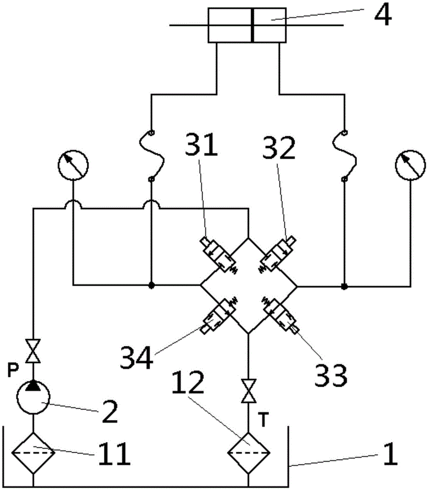
[0004] In order to solve the problems of using an oscilloscope to test the duty ratio of the digital valve under test, it takes a long time, the test efficiency is low, the test results are easily disturbed, and the test cost is high. The present invention proposes a digital valve test system. The digital valve test includes a fuel tank, Oil pump, oil inlet passage, four tested digital valves, piston hydraulic cylinder and oil return passage, the oil suction port of the oil pump is connected with the oil tank, the oil inlet passage is connected to the oil outlet, and the oil inlet The channel is provided with two branches, which are respectively connected to the oil inlet of the first digital valve to be tested and the oil inlet of the second digital valve to be tested, and the oil outlet of the first digital valve to be tested is connected to the piston The first cavity of the type hydraulic cylinder is connected, the oil outlet of the second tested digital valve is connected with the second cavity of the piston hydraulic cylinder, and the oil outlet of the first tested digital valve A branch pipe is arranged on the pipeline connecting the port with the first cavity of the piston hydraulic cylinder, and the branch pipe is connected with the oil inlet port of the fourth tested digital valve, and the oil outlet port of the second tested digital valve is connected with the The pipeline connected to the second cavity of the piston hydraulic cylinder is provided with a branch pipe, which is connected with the oil inlet of the third tested digital valve, and the oil outlet of the third tested digital valve is connected with the fourth tested digital valve. The oil outlets of the tested digital valves are all connected to one end of the oil return channel, and the other end of the oil return channel is connected to the oil tank

Method used


Image

  • Digital Valve Test System

Examples


Embodiment Construction

[0048] Such as figure 1 As shown, the digital valve test system of the present invention includes a fuel tank 1, an oil pump 2, an oil inlet passage P, a first digital valve 31 to be tested, a second digital valve 32 to be tested, a third digital valve 33 to be tested, and a fourth digital valve to be tested. The valve 34, the double-rod piston hydraulic cylinder 4 and the oil return channel T, the oil suction port of the oil pump 2 is connected with the oil tank 1 through the oil suction filter 11, the oil outlet of the oil pump 2 is connected with the oil inlet channel P, and the oil inlet channel P is provided with two branches, which are respectively connected with the oil inlet of the first tested digital valve 31 and the oil inlet of the second tested digital valve 32, and the oil outlet of the first tested digital valve 31 is connected with the hydraulic cylinder 4, the oil outlet of the second tested digital valve 32 is connected with the second cavity of the hydraulic...


PUM


Abstract

The invention relates to a test system of a digital valve. In order to solve the problems of using an oscilloscope to test the duty cycle of the digital valve under test, it takes a long time, the test efficiency is low, the test results are easily disturbed, and the test cost is high. channels, four tested digital valves, piston hydraulic cylinders and oil return channels, the oil pump suction port is connected to the fuel tank, and the oil outlet is connected to the oil inlet channel. The oil inlet channel has two branches, respectively connected to the first and second The oil inlet of the tested digital valve is connected, the oil outlet of the first tested digital valve is connected with the first cavity of the hydraulic cylinder, and the oil outlet of the second tested digital valve is connected with the second cavity of the hydraulic cylinder. The oil outlets of the third and fourth tested digital valves are connected to one end of the oil return channel, and the other end of the oil return channel is connected to the fuel tank. By using the digital valve test system of the present invention, the actual duty cycle of the digital valve can be accurately obtained, which provides guarantee for the practical application of the digital valve.

Description

technical field [0001] The invention relates to the field of hydraulic test systems, in particular to a test system capable of carrying out factory tests on digital valves. Background technique [0002] The digital valve is a valve group composed of multiple valves arranged in binary, and the flow coefficient of each valve is designed in binary sequence. The valves that make up the digital valve are on-off valves, that is, there are only two states: on and off. Therefore, their control can be achieved using solenoid valves or piston actuators with spring return. The switching speed of each valve is very fast, and the closing characteristics of each valve are also an important index to measure the performance of digital valves. It not only affects the flow capacity and leakage, but also affects the control quality of the control system. In order to ensure the closing characteristics of each valve, a spring return type actuator is usually used. At the same time, for a valve ...

Claims


Application Information

Patent Timeline
Patent Type & Authority Patents(China)
IPC IPC(8): F15B19/00
Inventor 许仰曾隆跃进朱小明王勇张磊方彪韩智慧吴振亚
Owner HAOGAO MECHATRONICS TECH SHANGHAI
Learn More