Glass tube coating device

A technology of coating device and glass tube, which is applied to the device and coating of surface coating liquid, can solve the problems of inapplicability to large-scale automatic production, low degree of automation, and low efficiency, and achieve large-scale automatic production, The effect of improving productivity

Active Publication Date: 2014-10-01
北京天瑞星光热技术有限公司
View PDF5 Cites 4 Cited by
  • Summary
  • Abstract
  • Description
  • Claims
  • Application Information

AI Technical Summary

Problems solved by technology

At present, more spin-coating coating methods are used in production. Small pulling equipment is used for laboratory research and coating of small glass materials. The manual method has low degree of automation, low efficiency, high cost, and poor stability, and requires multiple workers to manage during the production process, which increases the instability of the production process and is not suitable for large-scale automated production

Method used


Image

  • Glass tube coating device
  • Glass tube coating device
  • Glass tube coating device

Examples


Embodiment Construction

[0026] In order to describe the technical content, structural features, achieved goals and effects of the present invention in detail, the following will be described in detail in conjunction with the embodiments and accompanying drawings.

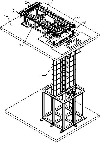
[0027] 参照附图,本发明提出一种玻璃管镀膜装置,包括机架1,所述机架1上设有:
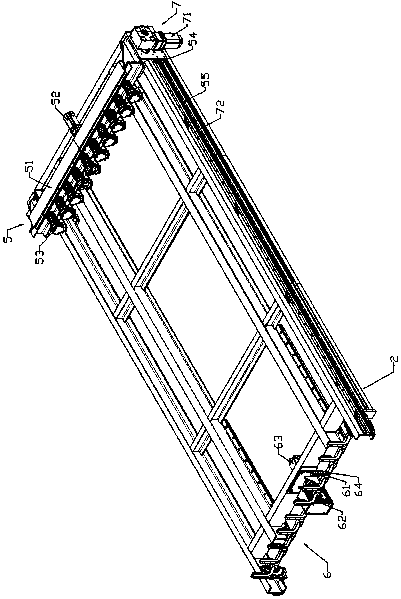
[0028] 玻璃放置架2;

[0029] 锁紧机构5,可滑动的设置在玻璃放置架2上,将玻璃管牢固固定;

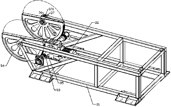
[0030] 翻转机构3,带动整个玻璃放置架2翻转90°;

[0031] 提升机构7,带动锁紧机构5在玻璃放置架2上移动;

[0032] Specifically, the turning mechanism 3 includes a bracket 31, a turning motor 32, a driving gear 33 and a driven gear 34, the driving gear 33 and the driven gear 34 mesh with each other, the driven gear 34 is a semicircular gear, and the semicircular The center of circle of the shaped gear is hinged with the support 31, the right-angled side is fixed with the glass placement frame 2, the turning motor 32 is fixed on the support 31, the turning motor 32 drives the driving gear 33 to rotate, drives the driven gear 34 to rotate, and further drives the glass placement s...


PUM


Abstract

The invention relates to a glass tube coating device which comprises a rack, wherein a glass holding frame, a locking mechanism, a turnover mechanism and a lifting mechanism are arranged on the rack; the turnover mechanism comprises a support, a turnover motor, a driving gear and a driven gear; the driving gear is meshed with the driven gear, and the driven gear is a semicircular gear; the circle center of the semicircular gear is articulated with the support, and the right-angle side of the semicircular gear is fixed to the glass holding frame; the turnover motor is fixed on the support, drives the driving gear to rotate, further drives the driven gear to rotate, and further drives the glass holding frame to rotate. Through the transition between the horizontal state and the vertical state of a glass tube and match with the longitudinal movement, the glass tube coating device with a novel structure realizes fully-automatic operation of feeding, rotating, decreasing infiltration coating, lifting, rotating and discharging and completely automated control, can realize large-scale automated production, and greatly improves the production efficiency.

Description

[0001] technical field [0002] 本发明涉及一种中高温太阳能集热管外玻璃管镀膜装置,尤其是一种采用提拉式镀膜方式的玻璃管镀膜装置。 [0003] Background technique [0004] 随着经济的发展,社会的进步,环境污染问题愈发严重,清洁能源的使用已经成为大家的共识。聚光太阳能发电(CSP,Concentrating Solar Power)作为零污染的清洁能源有着无可比拟的优势。槽式中高温太阳能发电技术是目前商业化使用时间最长、技术最成熟的太阳能光热发电产业,其中的核心器件——太阳能集热管性能优劣是决定发电站收益大小的主要因素,为了尽可能提高集热管性能,需要在外玻璃管上镀上一层增透膜。 [0005] 目前玻璃表面镀膜主要采用玻璃溶胶—凝胶方式,这种方式所使用的方法有 :旋涂镀膜法、提拉镀膜法。目前在生产中更多的则使用旋涂镀膜法,实验室研究和对小型玻璃材料的镀膜使用小型提拉设备,大型提拉设备多采取直上直下“浸润”式镀膜,但是上料和下料采取人工方式,自动化程度低、效率低、成本高、稳定性差,而且在生产过程中需要多个工人进行管理,增加了生产过程中的不稳定性,不适用于大规模自动化生产。 [0006] Contents of the invention [0007] 本发明的目的在于提供一种自动化控制、实现大规模自动化生产、生产效率高的玻璃管镀膜装置。 [0008] 为了解决上述技术问题,本发明提供一种玻璃管镀膜装置,包括机架,所述机架上设有: [0009] 玻璃放置架; [0010] 锁紧机构,可滑动的设置在玻璃放置架上,将玻璃管牢固固定; [0011] 翻转机构,带动整个玻璃放置架翻转90°; [0012] 提升机构,带动锁紧装置在玻璃放置架上移动; [0013] 所述翻转机构包括支架、翻转电机、主动齿轮及从动齿轮,所述主动齿轮与从动齿轮互相啮合,从动齿轮为半圆形齿轮,半圆形齿轮的圆心处与支架铰接,直角边与玻璃放置架相固定,翻转电机固定在支架上,翻转电机带动主动齿轮转动,从而带动从动齿轮转动,进一步的带动玻璃放置架转动; [0014] 所述提升装置包括提升电机、提升齿轮及齿条,所述提升电机及提升齿轮设置在锁紧装置上,所述齿条固定在玻璃...

Claims


Application Information

Patent Timeline
Patent Type & Authority Applications(China)
IPC IPC(8): B05C3/02B05C3/10B05C13/02
Inventor 范兵张磊杨兴王静杨元林
Owner 北京天瑞星光热技术有限公司
Why Eureka
Try Eureka