
Bookbinding Machine

A stapler, cutting and lifting technology, applied in binding and other directions, can solve the problems of damage energy, enlargement, etc., and achieve the effect of reliable binding

Active Publication Date: 2014-09-24
KOKUYO CO LTD
View PDF10 Cites 0 Cited by
  • Summary
  • Abstract
  • Description
  • Claims
  • Application Information

AI Technical Summary

Problems solved by technology

[0004] Therefore, there is a situation where the top portion of the louvers contacts the edge of the window of the plunging knife so that the top side of the louvers has to be inserted into the window while turning back unreasonably, so there is an unreasonable force applied to the louvers resulting in The problem that it breaks or the energy required for operation becomes larger

Method used


Image

  • Bookbinding Machine
  • Bookbinding Machine
  • Bookbinding Machine

Examples


Embodiment Construction

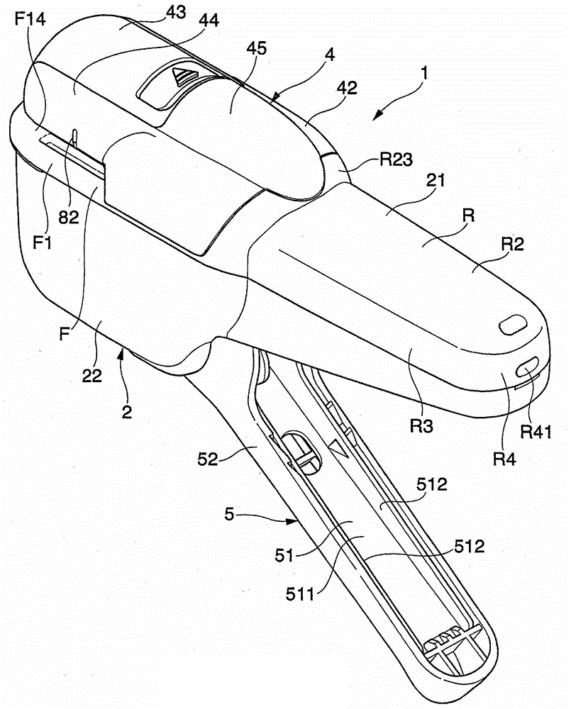
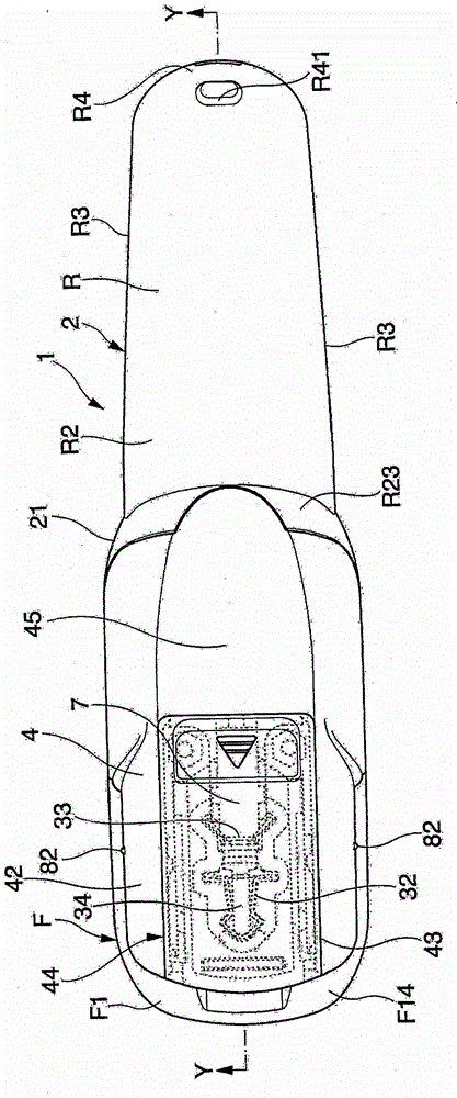
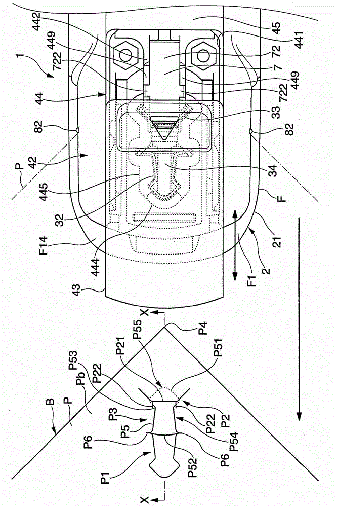
[0047] Refer to the side below Figure 1 to Figure 16 One embodiment of the present invention will be described.

[0048] Such as Figure 1 to Figure 16As shown, the stapler 1 according to this embodiment can form a through hole P1 and a cut hole P2 on a plurality of sheets of paper P, and make the cut and raised piece P5 cut and pulled up from the through hole P1 pass through the cut hole. P2, the booklet B is produced by binding these sheets P to each other.

[0049] Such as image 3 as well as Figure 4 As shown, the above-mentioned booklet B is a bundle of a plurality of sheets P, and these sheets P are joined together at a joint portion P3 set at a corner P4. The joining portion P3 is composed of a through hole P1 formed on each paper P by a perforating knife 32 inserted from the side Pa of the paper P, and a pull-up cut hole P2 adjacent to the through hole P1. is formed on each of the above-mentioned paper sheets P; Then, the corners P4 of the plurality of sheets o...


PUM


Abstract

The invention provides a bookbinding machine solving problems of damage to s slicing sheet due to irrational force applied thereon or large energy requirement for operation, so paper can be reliably binded. The bookbinding machine is characterized by comprising an insertion component, in which the slicing sheet is inserted into a window of an incision port and a binding component arranged different from the insertion part, wherein when the slicing sheet is inserted into the window of the incision port, the binding component can retracts to a position and the slicing sheet can be remained in a binding position when the slicing sheet is inserted into the window; and the binding component is arranged different from an incision blade.

Description

technical field [0001] The present invention relates to a stapler that binds the ends of a plurality of overlapped sheets together, in particular, a stapler that does not use a metal staple, and is called a so-called staple-less stapler. Background technique [0002] In the past, as such a stapler, a stapler having the following components is known: a perforating knife, which forms a through hole on a plurality of sheets of paper while forming a cut-up piece (cutting pull-up piece); The perforating knives are adjacently arranged and pierced through the cutting holes for locking the top side of the above-mentioned cut-up piece; the base part (ベース part) holds these perforating knives and the cutting knife; and the perforating table (パンチ table) holds A paper insertion gap is disposed on the base portion (for example, refer to Patent Document 1). In this stapler, the above-mentioned perforating knife and the cutting knife held by the above-mentioned base part are inserted into ...

Claims


Application Information

Patent Timeline
IPC IPC(8): B42B5/02
Inventor 青井宏和才川淳二
Owner KOKUYO CO LTD
Learn More