
Stapler

A stapler and staple technology, which is applied in the directions of bookbinding, staple staple tools, manufacturing tools, etc., to achieve the effects of improving appearance, ensuring safety, and excellent workability

Active Publication Date: 2010-01-20
MAX CO LTD
View PDF7 Cites 0 Cited by
  • Summary
  • Abstract
  • Description
  • Claims
  • Application Information

AI Technical Summary

Problems solved by technology

But once the stapler is unfolded, the staple remover (sheet metal blade) exposed from the base of the base turns to the top of the base of the handle portion, so there is fear of fingers being caught between the handle portion and the staple remover

Method used


Image

  • Stapler
  • Stapler
  • Stapler

Examples


Embodiment Construction

[0043] Hereinafter, typical embodiments of the present invention will be described using the drawings.

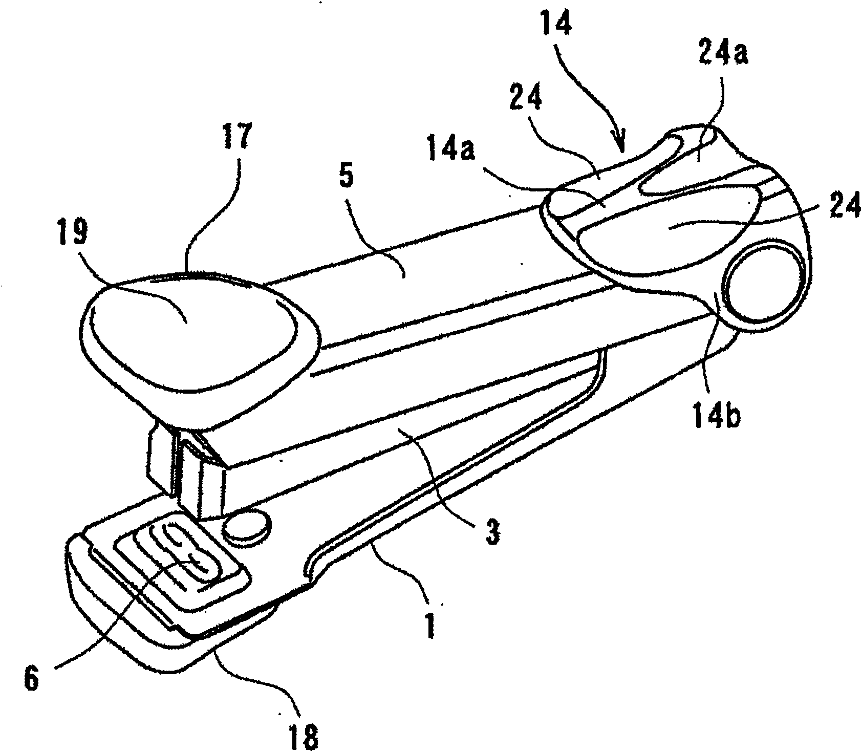
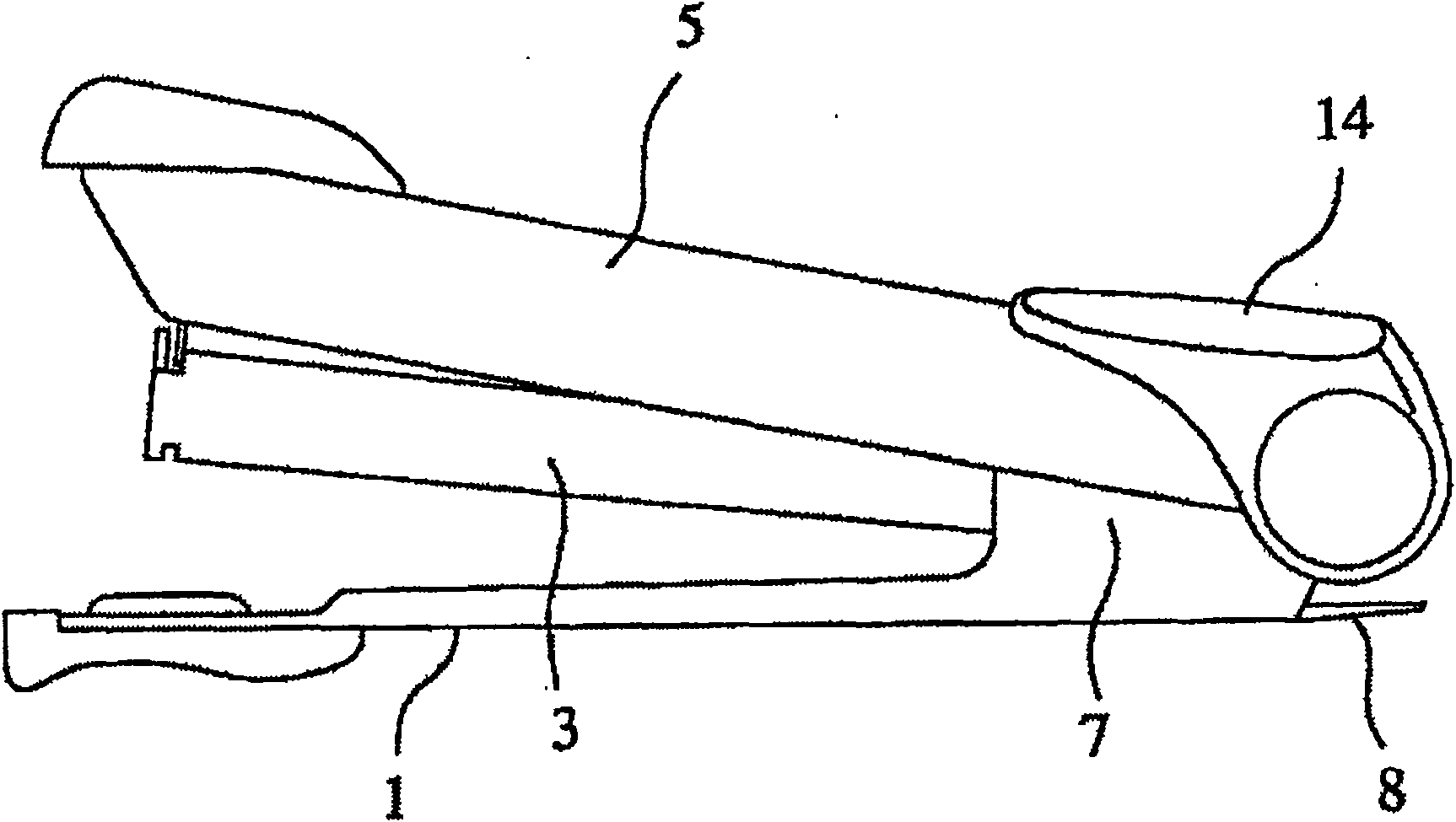
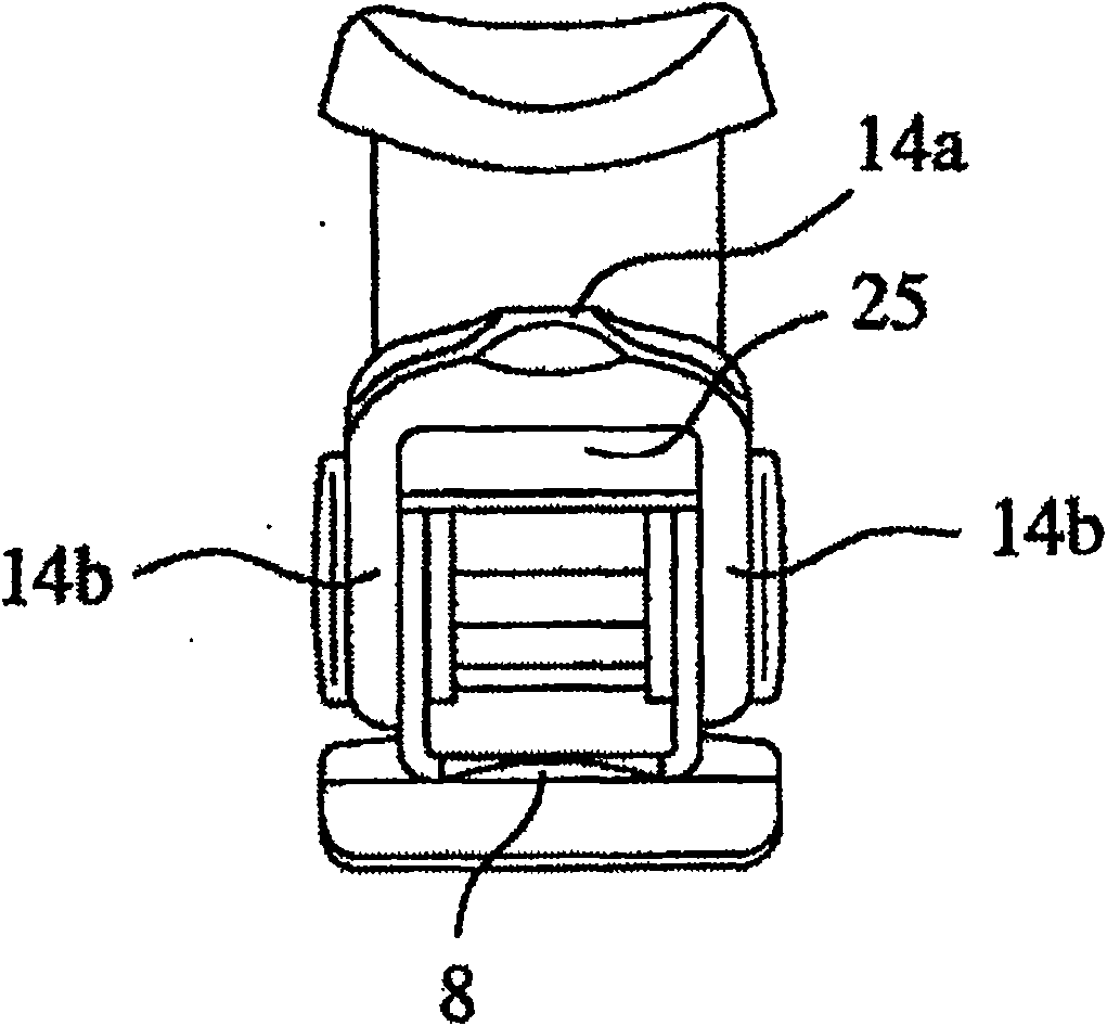
[0044] figure 1 It is the perspective view of the stapler of typical embodiment, and Fig. 2 (a) and Fig. 2 (b) are its side view and back view respectively, image 3 It is a sectional view showing the rough structure of the stapler. In this stapler, the nail box part 3 and the handle part 5 that accommodates a plurality of staples are rotatably supported by the support shaft 2 at the rear end of the base 1. The staples (not shown) in the box portion 3 face the driving plate 4 from which the staple paper is driven.

[0045] Clincher grooves 6 for bending legs of staples driven from the magazine unit 3 are formed at the front end of the base 1 . The support wall 7 is formed upright on the base. In addition, a thin plate-shaped staple remover 8 with a tapered front end protrudes from the rear end of the base 1 in order to remove the staples that bind the bound paper.

[0...


PUM


Abstract

A stapler having a magazine (3) for receiving a large number of staples, a handle (5) having at its forward end a driver plate (4) for expelling a staple received in the magazine (3) toward sheets of paper to be bound, and a base (1) having at its forward end a clincher groove (6) for bending the legs of the staple expelled from the magazine (3). The magazine (3) and the handle (5) are pivotally supported by a support shaft (2) at the rear end of the base (1). A synthetic resin protective cover (14) is attached to the base of the handle (5). The protective cover (14) covers the handle (5) over its upper surface and its side faces at which the end surfaces of the support shaft (2) are exposed.

Description

technical field [0001] The present invention relates to a base constituting a rotational fulcrum of a stapler mainly used for office work, and more particularly to a stapler with an improved base provided with a handle portion of a driving plate. Background technique [0002] Generally speaking, in this type of stapler, as shown in Japanese Patent Laid-Open No. 11-028682, the paper to be bound is clamped between a base with a crimping groove formed at the front end and a nail magazine filled with a plurality of staples, By pushing the handle on the upper part of the magazine toward the magazine side, the top staple is driven out by the driving plate provided on the handle so that it penetrates the paper to be bound and the foot of the staple after it penetrates. The paper is bound by the crimping groove of the base. [0003] In the existing stapler, in order to improve the fitting feeling on the upper side of the front end of the handle part that is in contact with the thum...

Claims


Application Information

Patent Timeline
Patent Type & Authority Patents(China)
IPC IPC(8): B25C5/02B42B4/00
Inventor 前森淳江崎周伊罗子知浩大桥司中村克也村冈洋一三轮俊英服部壮雄
Owner MAX CO LTD
Learn More