Touch module and manufacturing method thereof

一种触控模组、制造方法的技术,应用在仪器、电数字数据处理、数据处理的输入/输出过程等方向,能够解决只能贴附在LCD显示模组、电池功耗增加等问题,达到提高产品附加值、提高竞争力、节约生产成本的效果

Inactive Publication Date: 2014-09-17
BEIJING BOE OPTOELECTRONCIS TECH CO LTD
View PDF6 Cites 24 Cited by
  • Summary
  • Abstract
  • Description
  • Claims
  • Application Information

AI Technical Summary

Problems solved by technology

[0002] Electromagnetic touch technology, since it came out in 1964, is often used in smart digital boards, but at present, the electromagnetic antenna board inside the electromagnetic touch module generally adopts a back-attached structure. This electromagnetic antenna board is made of Composed of criss-cross metal wires, it is thick and non-transparent, so it can only be attached to the rear side of the LCD display module (LCD Module, LCM); at the same time, during the touch process, the above-mentioned back-attached structure makes the electromagnetic There is an LCM between the stylus and the electromagnetic antenna board. In order to achieve smooth touch, the electromagnetic signal strength of the electromagnetic stylus must be increased, so the power consumption of the battery will increase.

Method used


Image

  • Touch module and manufacturing method thereof
  • Touch module and manufacturing method thereof
  • Touch module and manufacturing method thereof

Examples


Embodiment Construction

[0020] The implementation manner of the present invention will be described in detail below in conjunction with specific embodiments and accompanying drawings.

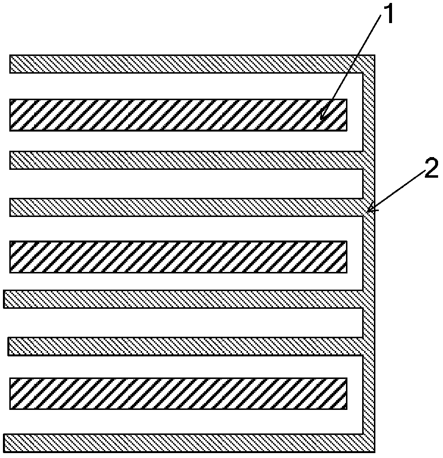
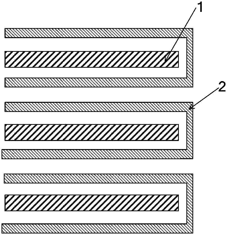
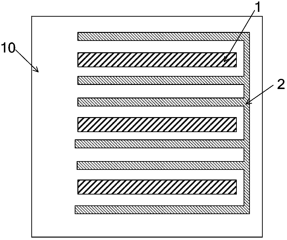
[0021] Figure 3 to Figure 6 It is a structural schematic diagram of the manufacturing process of the touch module of the present invention, Figure 7 It is a schematic diagram of the structure of each layer of the touch module of the present invention. The structure of the touch module of the present invention will be described in detail below in conjunction with the accompanying drawings:

[0022] A touch module provided by the present invention includes: a glass substrate 10 and a first transparent electrode layer 11 , a metal layer 12 , an insulating layer 13 , a second transparent electrode layer 14 and a protective layer 15 formed on the glass substrate 10 ;

[0023] Among them, such as image 3 As shown, the first transparent electrode layer 11 is formed on the glass substrate 10, and the first transparent el...


PUM


Abstract

A touch control module and a manufacturing method for the touch control module. The touch control module comprises: a substrates (10), and a first transparent electrode layer (11), a metal layer (12), an insulation layer (13), a second transparent electrode layer (14) and a protective layer (15) which are formed on the substrate (10). Both the first transparent electrode layer (11) and the second transparent electrode layer (14) comprise at least two electromagnetic touch control electrodes (2, 8) and at least two capacitive touch control electrodes (1, 7). Each of the electromagnetic touch control electrodes (2) and each of the capacitive touch control electrodes (1) of the first transparent electrode layer (11) are arranged in parallel and alternately. Each of the electromagnetic touch control electrodes (8) and each of the capacitive touch control electrodes (7) of the second transparent electrode layer (14) are arranged in parallel and alternately.

Description

technical field [0001] The invention relates to the field of touch technology, in particular to an electromagnetic touch and projected capacitive touch two-in-one module and a manufacturing method thereof. Background technique [0002] Electromagnetic touch technology, since it came out in 1964, is often used in smart digital boards, but at present, the electromagnetic antenna board inside the electromagnetic touch module generally adopts a back-attached structure. This electromagnetic antenna board is made of Composed of criss-cross metal wires, it is thick and non-transparent, so it can only be attached to the rear side of the LCD display module (LCD Module, LCM); at the same time, during the touch process, the above-mentioned back-attached structure makes the electromagnetic There is an LCM between the stylus and the electromagnetic antenna plate. In order to realize smooth touch, the electromagnetic signal strength of the electromagnetic stylus must be increased, thus re...

Claims


Application Information

Patent Timeline
Patent Type & Authority Applications(China)
IPC IPC(8): G06F3/044G06F3/046
CPCG06F3/046G06F3/044G06F2203/04106G06F3/0445G06F3/0446G06F3/047G06F2203/04103
Inventor 杨盛际
Owner BEIJING BOE OPTOELECTRONCIS TECH CO LTD
Why Eureka
Try Eureka