


Quick Research
Generate reliable direction feasibility study reports for your R&D in just a few steps.

Technical Q&A
Discover and master advanced knowledge NOW. Basics, ideas, possibilities, all at once.

Find Solutions
As an expert in R&D theories, this can generate solutions to your technical problems instantly.

Evaluate Feasibility
Analyze your overall solution with one click, know your potential R&D risks in advance.

Monitor Landscape
Get weekly tech updates, stay abreast of the latest tech innovations and key insights.
Submersible stirrer system for sewage treatment
A submersible mixer and sewage treatment technology, applied in water/sewage treatment, biological water/sewage treatment, water/sludge/sewage treatment, etc., can solve the problems of mixing, limitation, and no solution to the sludge layer, so as to improve the mixing effect, improve all-round effect
- Summary
- Abstract
- Description
- Claims
- Application Information
AI Technical Summary
Problems solved by technology
Method used
Image

Examples
Embodiment 1
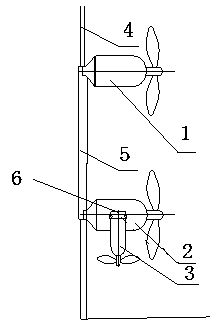
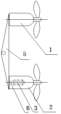
[0020] Such as figure 1 The embodiment of the submersible mixer system of the present invention is given, which is suitable for the occasions where the bottom of the sewage pool is relatively flat and the pool depth of the sewage pool is relatively deep, mainly including the first submersible mixer 1 and the second submersible mixer 2, the first submersible mixer 1 and the second submersible mixer 2 are installed on the connecting piece 5, while the connecting piece 5 is installed on the guide rod 4, and can move up and down along the guide rod 4 to adjust the position, and can be tightened after adjusting the position. The connector 5 is fixed on the pool wall of the sewage pool through the guide rod 4, the guide rod 4 is perpendicular to the bottom of the pool, and installed against the pool wall, the position of the guide rod 4 is equal to the distance from the two sides of the pool wall. The axes of rotation shafts of the first submersible mixer 1 and the second submersibl...
Embodiment 2
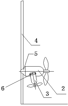
[0023] Such as figure 2 As shown, another embodiment of the submersible mixer system of the present invention is given, which is suitable for the occasions where the bottom of the sewage pool is relatively flat, and the width of the sewage pool is relatively wide, and the bottom of the pool is not too deep. It mainly includes a first submersible mixer 1 and a second submersible mixer 2, the axis of rotation of the first submersible mixer 1 and the second submersible mixer 2 are parallel to the bottom plane of the sewage tank, and the first submersible mixer 1 and the second submersible mixer The height of the second submersible mixer 2 is the same, so as to stir the sludge mixed water in the pool in a wide range in the sewage tank, the first submersible mixer 1 and the second submersible mixer 2 are installed on the connecting piece 5, and are connected at the same time Part 5 is installed on the guide rod 4, and can move up and down along the guide rod 4 to adjust the positi...
PUM
 Abstract
Description
Claims
Application Information
 - R&D Engineer
- R&D Manager
- IP Professional
- Industry Leading Data Capabilities
- Powerful AI technology
- Patent DNA Extraction
Browse by: Latest US Patents, China's latest patents, Technical Efficacy Thesaurus, Application Domain, Technology Topic, Popular Technical Reports.
© 2024 PatSnap. All rights reserved.Legal|Privacy policy|Modern Slavery Act Transparency Statement|Sitemap|About US| Contact US: help@patsnap.com