A smart locker based on mcu

A locker and intelligent technology, applied in the field of lockers, can solve the problems of hindering the placement of items, the scale of the lifting device is large, and it is difficult to improve the aesthetic feeling, and achieves the effect of simple appearance, safe use, and increased space utilization.

Inactive Publication Date: 2016-04-13
ZHEJIANG UNIV
View PDF7 Cites 0 Cited by
  • Summary
  • Abstract
  • Description
  • Claims
  • Application Information

AI Technical Summary

Problems solved by technology

[0003] The lockers in the prior art generally use a direct switch to control the motor transmission to realize the lifting of the entire locker. The main problem of this is that the lifting device that makes the locker lift as a whole is large in scale, and the drive can be seen from the outside. Mechanism makes it difficult to improve the aesthetics, and the falling of the locker also hinders the placement of items under the cabinet, which cannot save space

Method used


Image

  • A smart locker based on mcu
  • A smart locker based on mcu
  • A smart locker based on mcu

Examples


Embodiment 1

[0066] See attached Figure 4 , Figure 19~Figure 21 . Detect if a key is pressed. When button 16 on the control panel, a certain drawer button is pressed, a P1 port of the AT89C51 connected to the button becomes low level, and at this moment, the drawer layer to be opened will be displayed on the LCD display. The MCU detects the pressed drawer layer through the query method, and the software programming jumps to the motor execution program.

Embodiment 2

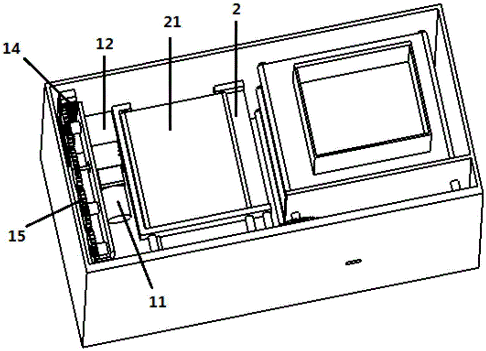
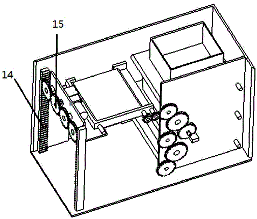
[0068] See attached Figure 1~Figure 2 . Lifting plate 2 falls vertically to place conveyor belt 5 ahead. The P3.4~P3.7 pins of the chip AT89C51 output PWM control signals. The ULN2003 chip controls the rotation of the lifting motor 11. The worm 18 coaxial with the lifting motor 11 drives the turbine 19 to rotate. The turbine 19 is coaxial with a lifting gear 15. Lifting gear 15 rotates and drives the gear meshed with it to rotate in the opposite direction, and lifting plate 2 vertically falls to the place ahead of the corresponding conveyor belt 5, and lifting plate 2 maintains the same level as the corresponding placing conveyor belt 5. At this time, the chip AT89C51 outputs a delay signal and waits for the drawer 4 to move to the lifting plate 2. In order to fix the lifting gear 15, the worm gear 12 is used to realize self-locking, because the thread opening angle of the worm 18 is small, which is smaller than the pressure angle of the worm gear 19. , so the worm wheel 19...

Embodiment 3

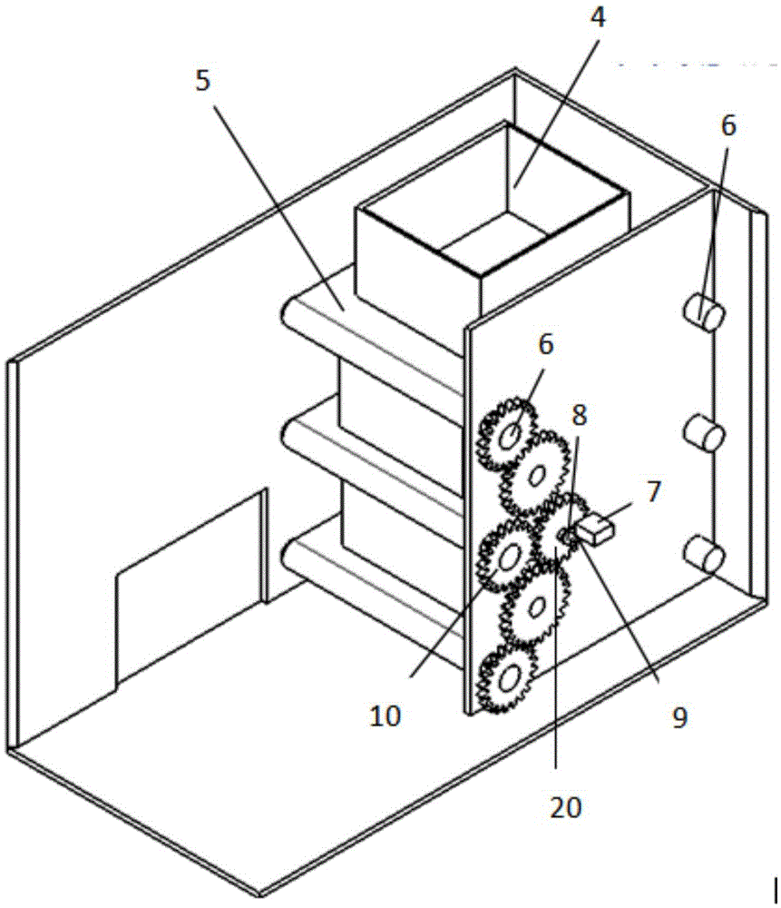
[0070] See attached image 3 , Figure 6 , Figure 17 , Figure 18 . The drawer 4 is moved onto the lifting plate 2 by placing the conveyor belt 5 and the lifting plate conveyor belt 21 . The P2.7 pin of the chip AT89C51 first outputs a control signal to control the rotation angle of the steering gear 7. The steering gear 7 adjusts the position of the transmission motor 8 and the positioning gear 20 through the swing arm 9, so that the positioning gear 20 meshes with the corresponding transmission gear 10 , when the positioning gear 20 meshes with the transmission gear 10, the P3.0~P3.3 pins output PWM control signals, and the ULN2003 chip controls the rotation of the transmission motor 8, and the output shaft of the transmission motor 8 is coaxially connected with the positioning gear 20 to drive the positioning The gear 20 rotates, and the transmission gear 10 rotates to drive the placement conveyor belt 5 to move, and the drawer 4 moves forward on the placement conveyor...


PUM


Abstract

The invention discloses an intelligent storage cabinet based on an MCU. Two sides of a cabinet body are internally provided with a lifting mechanism and a conveying bearing mechanism; a drawer outlet is formed in the lower part of the cabinet body; the conveying bearing mechanism comprises multiple layers of conveyor belt mechanisms in parallel, a steering engine, a transmission motor, a swing arm and a positioning gear; each layer of conveyor belt mechanism comprises a bearing conveyor belt, a conveyor belt shaft and a transmission gear; the lifting mechanism comprises a lifting plate, a lifting motor, a worm and worm wheel mechanism, a lifting plate gear, a rack and a lifting gear; when being taken out, a drawer is moved to the lifting plate through the bearing conveyor belt and a lifting plate conveyor belt, and then is moved to the drawer outlet through the lifting mechanism to be taken out; when being put back, the drawer is placed on the lifting plate at the drawer outlet, then is moved to the same horizontal height with the bearing conveyor belt by the lifting mechanism, and is moved to the bearing conveyor belt on the layer through the lifting plate conveyor belt and the bearing conveyor belt. The intelligent storage cabinet has a simple structure, is convenient in operation, and is favorable for people to get items placed in high positions of the storage cabinet.

Description

technical field [0001] The invention relates to a locker suitable for being installed in a high place, in particular to an MCU-based intelligent locker. Background technique [0002] Along with the raising of people's living standard, various lockers come into daily life, are used for taking and placing articles. In order to make full use of the space, keep the environment clean and tidy, and increase the operating space at the same time, placing the locker at a high place is a common phenomenon in homes and other occasions. It can be used in kitchens, bedrooms, study rooms, pharmacies, supermarkets, etc. In the storage room, when placing or picking up objects, you only need to select the open drawer layer through the buttons on the outside of the cabinet or the wireless remote control, and the control circuit will immediately control the motor to rotate, and move the drawer to the bottom layer to open, which not only makes full use of the upper layer. The space is also con...

Claims


Application Information

Patent Timeline
Patent Type & Authority Patents(China)
IPC IPC(8): A47B51/00
Inventor 欧晨曦陆玲霞
Owner ZHEJIANG UNIV
Why Eureka
Try Eureka