
A High Performance Combined Rectangular Waveguide

A rectangular waveguide and combined technology, which is applied in the field of high-performance combined rectangular waveguides, can solve the problems that the rectangular waveguide cavity cannot work normally, the influence degree is increased, etc., so as to improve the microwave transmission characteristics, good contact state, and solve the problem of microwave leakage. Effect

Inactive Publication Date: 2016-09-07
THE 41ST INST OF CHINA ELECTRONICS TECH GRP
View PDF3 Cites 0 Cited by
  • Summary
  • Abstract
  • Description
  • Claims
  • Application Information

AI Technical Summary

Problems solved by technology

When the two waveguide cavity components are pressed tightly, due to the existence of the flatness error of the waveguide cavity components, the contact state of the two waveguide cavity components actually changes from surface contact to point contact 103, as shown in Figure 5 As shown, looking along the extending direction of the rectangular waveguide cavity 102, there is a tiny gap 104 at the junction 101 located on both sides of the rectangular waveguide cavity. This tiny gap will have a serious impact on the transmission characteristics of the rectangular waveguide cavity in the millimeter wave band, especially When the operating frequency reaches the submillimeter wave frequency band, the influence will increase sharply, and even cause the rectangular waveguide cavity to fail to work normally

Method used


Image

  • A High Performance Combined Rectangular Waveguide
  • A High Performance Combined Rectangular Waveguide
  • A High Performance Combined Rectangular Waveguide

Examples


Embodiment 1

[0029] combine Figure 6 to Figure 11 As shown, a high-performance combined rectangular waveguide includes two waveguide cavity components 201 and 202, and a rectangular waveguide cavity 203 extending along the transmission direction of microwave signals is provided at the connection of the waveguide cavity components. Viewed along the extending direction of the rectangular waveguide cavity 203, a first contact portion 204 and a second contact portion 205 are respectively provided at the junction located on both sides of the rectangular waveguide cavity 203, next to the rectangular waveguide cavity, and the first contact portion 204 and the second contact portion The extending direction of the contact portion 205 is the same as that of the rectangular waveguide cavity 203 .

[0030] There is one first contact part 204 , which is arranged on one of the waveguide cavity components 201 or 202 . A first contact surface is formed between the first contact portion 204 and another w...

Embodiment 2

[0039] Except that the following technical features are slightly different from some of the technical features in Embodiment 1, the rest of the technical features not mentioned in Embodiment 2 are completely the same as those in Embodiment 1, and will not be described in detail here.

[0040] Such as Figures 12 to 15 As shown, there are two first contact portions 204 , which are respectively arranged on the two waveguide cavity assemblies 201 and 202 , and a first contact surface is formed between the two first contact portions 204 .

[0041] There are two second contact portions 205 , which are respectively arranged on the two waveguide cavity assemblies 201 and 202 . A second contact surface is formed between the two second contact portions 205 .

[0042] The first contact portion 204 and the second contact portion 205 have the same thickness. The sum of the thicknesses of the two first contact portions 204 should be kept between 0.3mm˜1mm.


PUM


Abstract

The invention discloses a high-performance combined rectangular waveguide, which comprises two waveguide cavity components. A rectangular waveguide cavity extending along the transmission direction of microwave signals is arranged at the connection of the waveguide cavity components. Next to the rectangular waveguide cavity, a first contact portion and a second contact portion are respectively provided, and the extension direction of the first contact portion and the second contact portion is the same as that of the rectangular waveguide cavity; there is at least one first contact portion, A first contact surface is formed between the first contact part and the first contact part, or another waveguide cavity component; there is at least one second contact part, between the second contact part and the second contact part, or another waveguide cavity component The second contact surface is formed between them; if the width of the first contact surface is A, the width of the second contact surface is B, and the width of the section of the rectangular waveguide cavity intercepted by the plane where the connection is located is C, then A, B, and C exist as follows Proportional relationship: 3A≤C≤7A, 3B≤C≤7B. The invention can ensure that the combined rectangular waveguide has good transmission characteristics.

Description

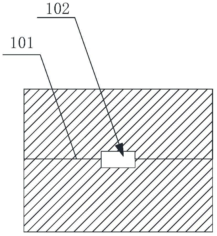
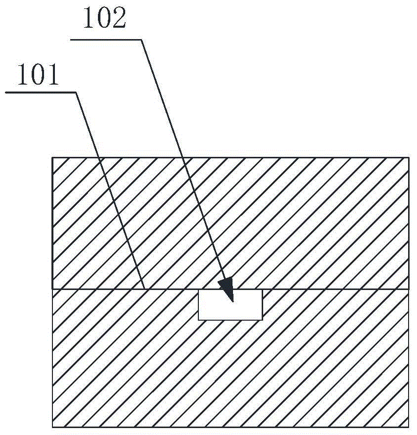
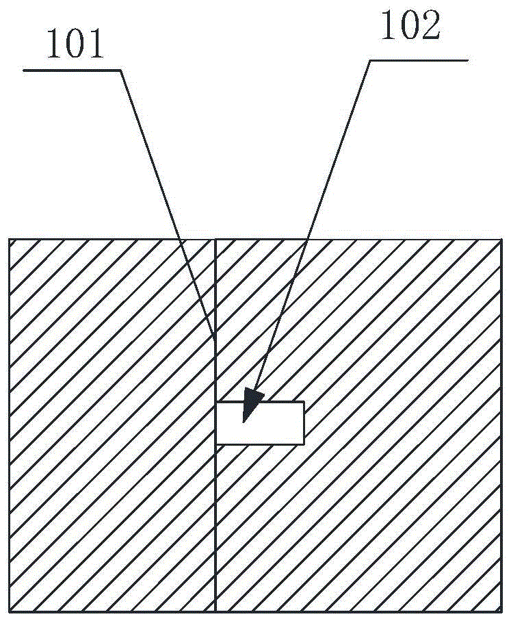
technical field [0001] The invention relates to a high-performance combined rectangular waveguide. Background technique [0002] There are a large number of waveguide cavity components in millimeter wave communication and test systems. For most rectangular waveguide cavity components, various circuits need to be integrated inside. In order to facilitate circuit assembly, a combined rectangular waveguide is usually required. Figure 1 to Figure 4 Several common structural forms of combined rectangular waveguides are shown. Depend on Figure 1 to Figure 4 It can be seen that the combined rectangular waveguide is composed of two waveguide cavity components, which are fixed by screws, and a rectangular waveguide cavity 102 is formed at the junction 101 of the two waveguide cavity components for transmitting microwaves. The contact area of ​​the two waveguide cavity components is Obviously larger than the cross-sectional area of ​​the rectangular waveguide cavity 102 taken by th...

Claims


Application Information

Patent Timeline
Patent Type & Authority Patents(China)
IPC IPC(8): H01P3/12
Inventor 唐波王俭超孙海波赵秉玉
Owner THE 41ST INST OF CHINA ELECTRONICS TECH GRP
Learn More