
Measurement method of thermal contact resistance between thin-layer materials based on 3ω method

A technology of thin-layer materials and testing methods, applied in the direction of material thermal development, etc., can solve problems such as difficult to guarantee measurement accuracy, complicated formula derivation, and many factors in measurement results, so as to achieve fast measurement, avoid complex formula derivation and calculation, geometric low size effect

Active Publication Date: 2016-07-06
NANJING UNIV OF SCI & TECH
View PDF4 Cites 0 Cited by
  • Summary
  • Abstract
  • Description
  • Claims
  • Application Information

AI Technical Summary

Problems solved by technology

[0003] In the experimental measurement method of thermal contact resistance, the traditional steady-state method is mainly used, but the steady-state method needs to insert a thermocouple into the upper and lower two samples to be tested during the measurement process. In order to obtain the axial temperature gradient of the sample, it is necessary Multiple temperature measurement points are arranged, so there are high requirements for the geometric dimensions of the sample, and it is difficult to measure the contact thermal resistance between thin-layer materials with a thickness of less than 50mm. up to 8 hours
Although various transient methods (mainly laser photothermal measurement method, laser flash method, and laser photoacoustic method) have the ability to measure the contact thermal resistance between thin-layer materials, there are many factors that affect the measurement results, and the derivation of the formula is complicated. Accuracy is difficult to guarantee

Method used


Image

  • Measurement method of thermal contact resistance between thin-layer materials based on 3ω method
  • Measurement method of thermal contact resistance between thin-layer materials based on 3ω method
  • Measurement method of thermal contact resistance between thin-layer materials based on 3ω method

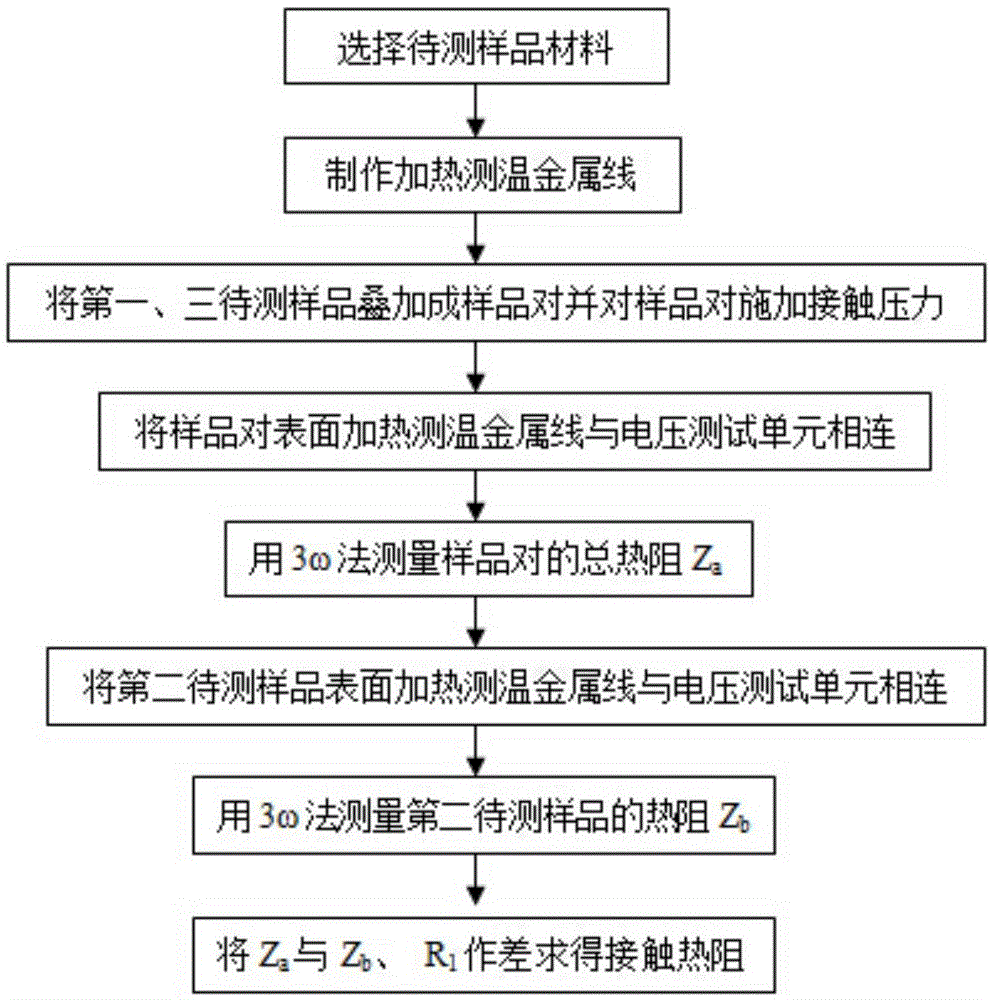
Examples


Embodiment Construction

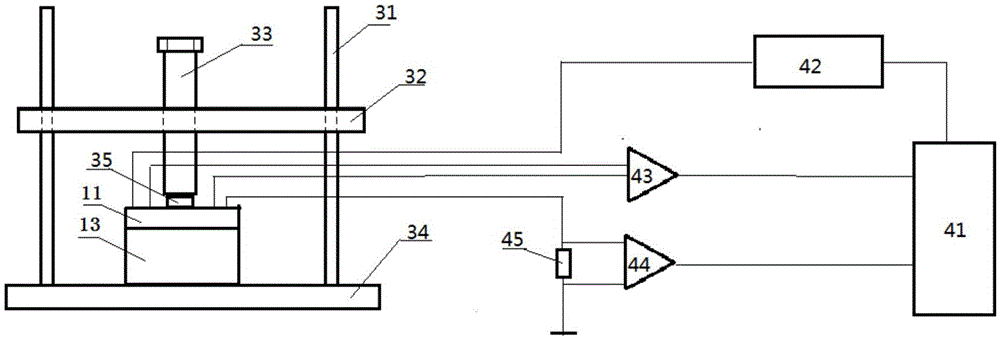
[0024] combine Figure 1 to Figure 6 :

[0025] A test method for contact thermal resistance between thin-layer materials based on the 3ω method, the test steps for realizing the method are as follows:

[0026] Step 1: Select the materials of the first sample to be tested 11 and the second sample to be tested 12, and select a third sample to be tested 13 that is the same material as the second sample to be tested 12;

[0027] Step 2: Make a heating and temperature measuring metal wire 21 on one side of the first sample to be tested 11, and make a heating and temperature measuring metal wire 22 on one side of the second sample to be tested. If the first sample to be tested 11 or The second sample to be tested 12 is a metal material, then first deposits a layer of insulating film on the surface of the heating and temperature measuring metal wire;

[0028] Step 3: Place the first sample to be tested 11 with its heating and temperature measuring metal wire 21 facing up on the th...


PUM

PropertyMeasurementUnit
thicknessaaaaaaaaaa
thicknessaaaaaaaaaa
thicknessaaaaaaaaaa

Abstract

The invention provides a method for testing the contact thermal resistance between thin-layer materials based on the 3ω method. The test method is to use the 3ω method to measure the total thermal resistance of the sample pair to be tested and the comparison sample respectively, and then obtain the contact resistance by calculating the difference. thermal resistance. The measurement method is as follows: the first sample to be tested and the third sample to be tested are superimposed and placed to form a pair of thermal contact resistance samples to be tested; the second sample to be tested is used as a comparison object; The size of the contact pressure; connect the voltage test unit with the heating and temperature measuring metal wire on the surface of the sample to be tested, and measure the total thermal resistance of the pair of samples to be tested and the second sample to be tested, and finally obtain the contact thermal resistance by making a difference. The method can quickly measure the contact thermal resistance between thin-layer materials, and the measurement principle is simpler than other transient methods.

Description

technical field [0001] The invention belongs to the technical field of contact thermal resistance measurement, in particular to a method for testing the contact thermal resistance between thin-layer materials based on the 3ω method. Background technique [0002] With the rapid development of the electronics industry, the packaging density of electronic devices is getting higher and higher, and the smaller and smaller packaging volumes make the heat dissipation problem of electronic equipment more and more prominent. Studies have pointed out that temperature is one of the main factors affecting the stability and reliability of electronic equipment in electronic systems, and 55% of failures are caused by unreasonable operating temperatures of devices. The contact thermal resistance is an important factor affecting the heat dissipation capability of electronic devices. The existence of contact thermal resistance will definitely hinder the transfer of heat flow on the contact in...

Claims


Application Information

Patent Timeline
Patent Type & Authority Patents(China)
IPC IPC(8): G01N25/20
Inventor 宣益民李强麻景峰
Owner NANJING UNIV OF SCI & TECH
Learn More