
A kind of micro-device and packaging mold for micro-device

A technology for micro-devices and molds, applied in piezoelectric devices/electrostrictive devices, microstructure devices, piezoelectric/electrostrictive/magnetostrictive devices, etc., which can solve the problems of device contamination and high requirements for repackaging , to ensure the packaging molding, prevent the spread of colloid, and ensure the effect of protection

Active Publication Date: 2017-05-24
宁卡赛科技(上海)有限公司
View PDF6 Cites 0 Cited by
  • Summary
  • Abstract
  • Description
  • Claims
  • Application Information

AI Technical Summary

Problems solved by technology

But this is easy to cause contamination to the device, and the requirements for repackaging are relatively high

Method used


Image

  • A kind of micro-device and packaging mold for micro-device

Examples


Embodiment Construction

[0017] The present case will be further described below in conjunction with specific embodiments and accompanying drawings.

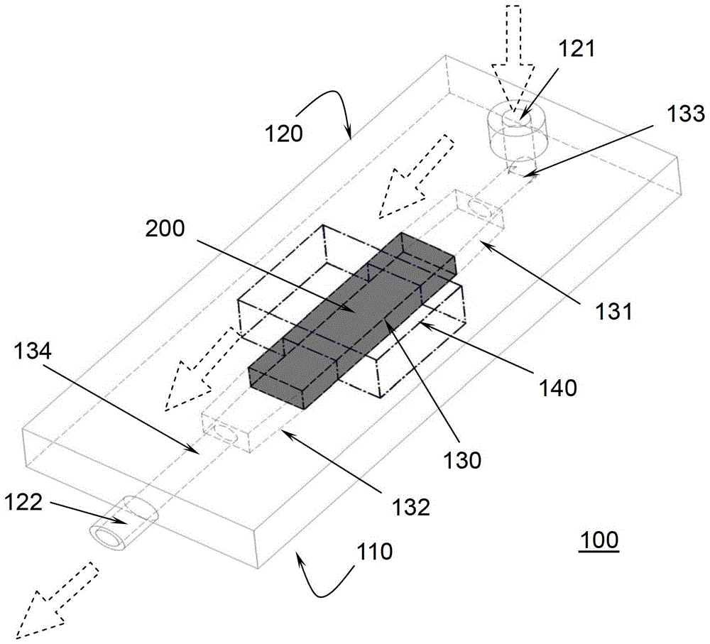
[0018] See figure 1 , figure 1 A packaging mold 100 for a micro device 200 provided by a preferred embodiment of the present invention and a micro device 200 molded by the packaging mold 100 are shown. The micro-device 200 is shown in the form of a black cuboid, which has an internal channel (not shown) connecting its front and rear ends. The packaging mold 100 includes a substrate 110 and a cover plate 120 that are covered with each other, wherein the cover plate 120 includes an inlet 121 disposed on the top thereof, and an outlet 122 disposed on one side thereof.

[0019] When the cover plate 120 and the substrate 110 cover each other, a sealed cavity 130 closely matching the size of the micro device 200 is formed, and an inflow cavity 131 and an outflow cavity 132 are formed at two ends of the sealed cavity 130 . Wherein, the sealed cavity 130 is ...


PUM


Abstract

The invention relates to a packaging mold of a microdevice. The packaging mold comprises a substrate and a cover plate covering the substrate. After the cover plate covers the substrate, a sealing chamber used for fixedly receiving the microdevice is formed. Left and right sides of the microdevice are provided with connection chambers. Pins of the microdevice are arranged in the connection chambers.

Description

technical field [0001] The invention relates to a packaging mold, in particular to a packaging mold for micro devices. [0002] The invention also relates to a micro-device encapsulated and formed by the encapsulation mold. Background technique [0003] A micro-device is a structure that contains one or more active components and can be composed of a variety of materials. It often works in high temperature, high humidity, or harsh acid-alkaline environments. Micro-devices communicate with the external environment for data, information and energy. The exchange depends on the interface function to achieve. In micro-devices, common interfaces include biomedical interfaces, microfluidic interfaces, etc. The interface is a key technical problem that must be solved in micro-device packaging, and directly determines whether the device or system function can be realized. For the biomedical interface, it is required that the system package can resist chemical corrosion during use, ...

Claims


Application Information

Patent Timeline
Patent Type & Authority Patents(China)
IPC IPC(8): B81C99/00B81B3/00
Inventor 谢元华姜彬
Owner 宁卡赛科技(上海)有限公司
Learn More