Actuating device for a rotatable closure part of a valve

A technology of operating devices and locking parts, which is applied in the direction of valve operating/release devices, valve devices, fluid pressure actuating devices, etc., and can solve problems such as rotation angle restrictions

Active Publication Date: 2014-09-03
GEA TUCHENHAGEN GMBH
View PDF18 Cites 12 Cited by
  • Summary
  • Abstract
  • Description
  • Claims
  • Application Information

AI Technical Summary

Problems solved by technology

So this is stroke-dependent and thus the indirect rotation angle limitation

Method used


Image

  • Actuating device for a rotatable closure part of a valve
  • Actuating device for a rotatable closure part of a valve
  • Actuating device for a rotatable closure part of a valve

Examples


Embodiment Construction

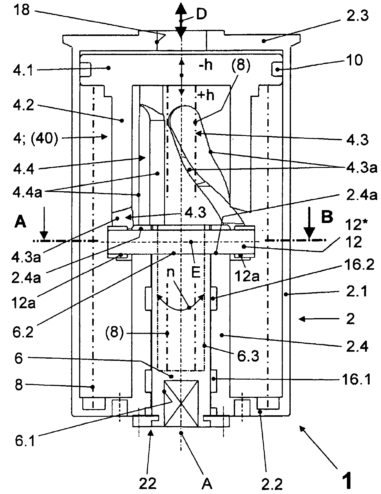
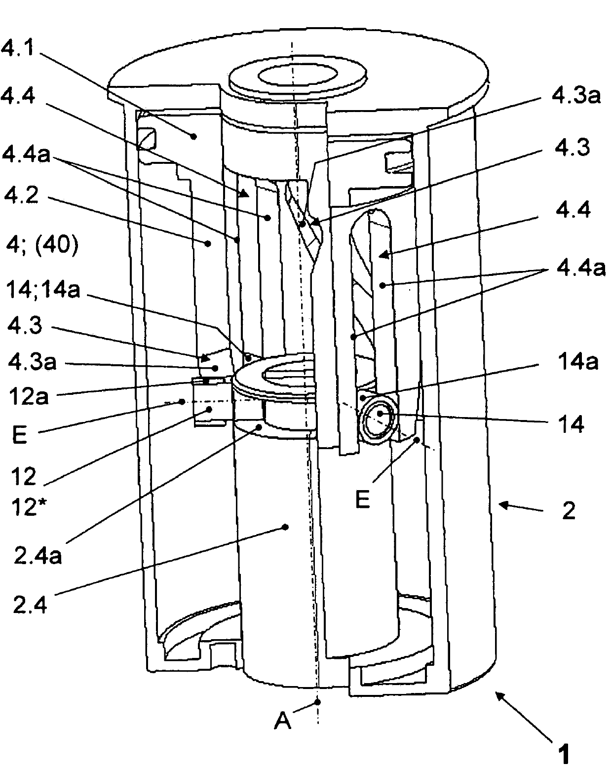
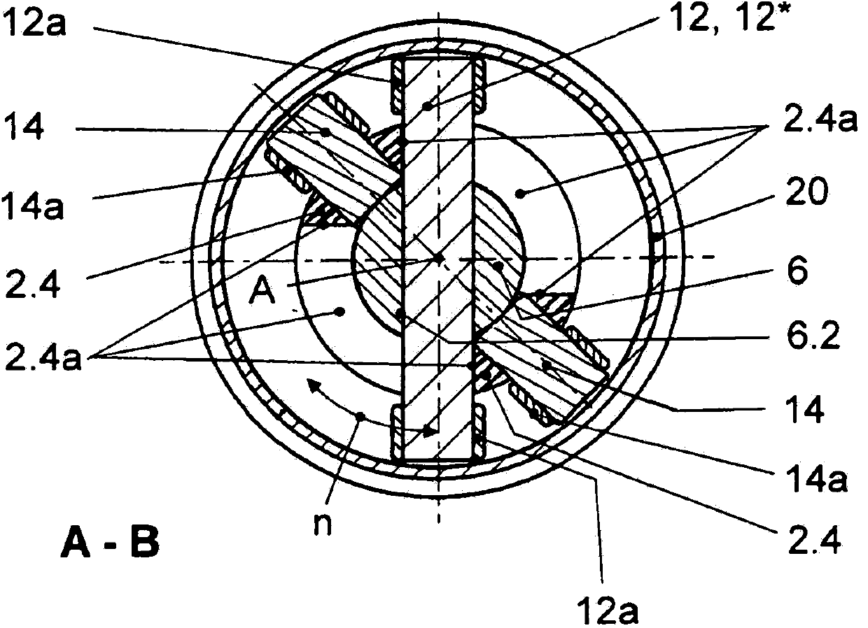
[0042] Operating device 1 for a rotatable closure of a valve ( Figures 1 to 6 ) with reference to the view position on the underside through the lantern housing 23 ( Figure 5 ) is connected to the latch (valve with latch not shown). Lantern housing 23 is screwed with lantern flange 23 a , preferably by means of screws 24 and nuts 25 , to first housing end face 2 . 2 of housing 2 of operating device 1 . The exemplary embodiment is a pneumatically actuatable actuating device 1 (pneumatic pressure medium D), also referred to as a rotary drive, for valves, which are also referred to as disk valves or throttle valves. The operating device 1 can also be acted upon with the hydraulic pressure medium D with corresponding adaptations.

[0043] The operating device 1 includes a housing 2 ( figure 1 , 2 , 5) In the housing there is arranged a sealing with the aid of a piston seal 10 relative to the cylindrical housing circumferential shell 2.1, which can be acted on one side with a...


PUM


Abstract

The invention relates to an actuating device 1 for a rotatable closure part of a valve, in particular a pneumatically or hydraulically actuable rotary drive for a disc valve or throttle valve, according to the preamble of claim 1. The invention is based on the problem of providing an actuating device of the generic type which is of simple construction, has high stability in the region of the mounting of the drive shaft and in the region of the rectilinear and curved guide which is arranged in the driving piston, and has a stroke-independent, direct rotary-angle limiting means with accuracy which is as great as possible. This is achieved by virtue of the fact that the drive shaft (6) is mounted radially on two sides in a bearing sleeve (2.4) which engages into the housing (2), is connected fixedly to the latter and ends in the latter, that the piston skirt (4.2; 40b.2) is mounted axially displaceably and radially on the outer circumferential surface of the bearing sleeve (2.4), and that the at least one drive pin (12) experiences a stroke-independent, direct limiting of the rotational movement thereof about the rotational axis (A) by way of stop means (2.4a) which are provided in the bearing sleeve (2.4).

Description

technical field [0001] The invention relates to an actuating device for a rotatable closure of a valve, in particular a pneumatically or hydraulically actuatable rotary drive for a disc valve or a throttle valve, the actuating device has a housing, Arranged in the housing is a drive piston that is sealed against the cylindrical housing circumferential casing and can be acted upon on one side with a pressure medium, the drive piston preferably having a tubular piston rod; the drive shaft, the The drive shaft leads out of the housing on one side and drives the locking element in rotation indirectly or directly, wherein the drive piston either carries out an axial displacement movement against the action of at least one return spring when pressure medium is applied to one side, or alternately (wechselseitig) carry out a reciprocating displacement movement when loaded with a pressure medium, wherein the piston rod is guided axially in the housing via at least one axial groove form...

Claims


Application Information

Patent Timeline
Patent Type & Authority Applications(China)
IPC IPC(8): F16K31/163F16K31/528F15B15/06
CPCF16K31/1221F16K31/5282F15B15/068F16K31/16
Inventor J·布尔梅斯特M·聚德尔
Owner GEA TUCHENHAGEN GMBH
Why Eureka
Try Eureka