High-power factor valley-filled circuit for driving switch type load and switching power supply

A high power factor, valley-filling circuit technology, applied in the electronic field, can solve the problems of increased number of components, no adjustment, low power factor, etc., and achieve high power factor, simple structure, and small size.

Inactive Publication Date: 2014-09-03
熊晓丹
View PDF6 Cites 3 Cited by
  • Summary
  • Abstract
  • Description
  • Claims
  • Application Information

AI Technical Summary

Problems solved by technology

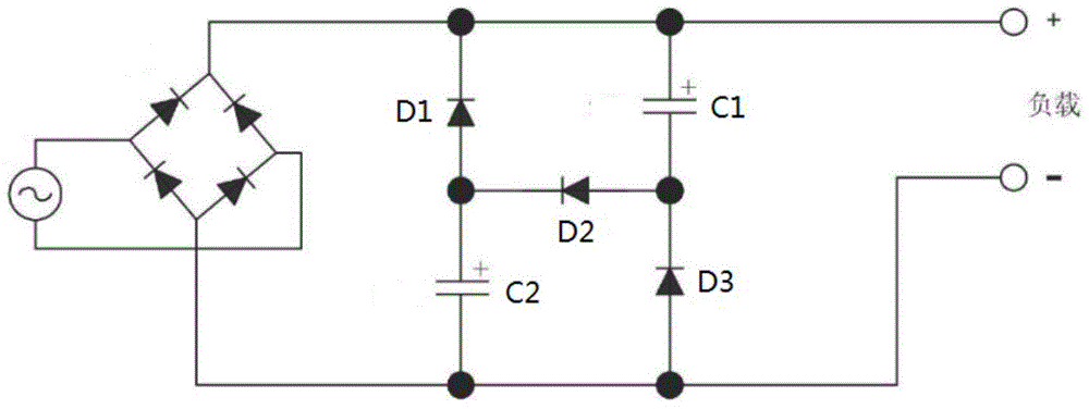
[0004] The minimum output voltage of this passive valley filling circuit is half of the peak value of the AC voltage, it is not adjustable, its application is limited, and its power factor is not high, generally less than 0.9
Of course, a multi-level expansion method can also be used, but at this time the number of components will increase greatly, and the cost will also increase accordingly, so it is almost not used in practical applications.

Method used


Image

  • High-power factor valley-filled circuit for driving switch type load and switching power supply
  • High-power factor valley-filled circuit for driving switch type load and switching power supply
  • High-power factor valley-filled circuit for driving switch type load and switching power supply

Examples


Embodiment Construction

[0051] The following will clearly and completely describe the technical solutions in the embodiments of the present invention with reference to the accompanying drawings in the embodiments of the present invention. Obviously, the described embodiments are only some, not all, embodiments of the present invention. Based on the embodiments of the present invention, all other embodiments obtained by persons of ordinary skill in the art without making creative efforts belong to the protection scope of the present invention.

[0052] In order to make the above objects, features and advantages of the present invention more comprehensible, specific implementations of the present invention will be described in detail below in conjunction with the accompanying drawings.

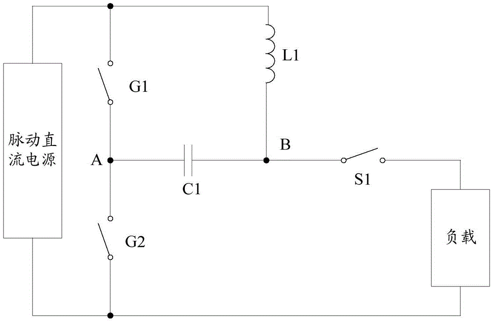
[0053] see figure 2 , which is a schematic diagram of Embodiment 1 of a high power factor valley filling circuit for driving a switching load provided by the present invention.

[0054] This embodiment provides a high ...


PUM


Abstract

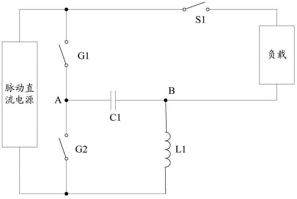
The invention provides a high-power factor valley-filled circuit for driving a switch type load and a switching power supply. The high-power factor valley-filled circuit comprises three ports, wherein the first end of a first switching tube is the first port; the first end of the first switching tube is connected with the positive output end of a pulsating DC power supply, and the second end of the first switching tube is connected with a first joint; the first end of a second switching tube is connected with the first joint, and the second end of the second switching tube is connected with the negative output end of the pulsating DC power supply; the second end of the second switching tube is the second port; the first end of a first inductor is connected with the positive output end of the pulsating DC power supply, and the second end of the first inductor is connected with a second joint; the second joint is the third port; the first end of a first capacitor is connected with the first joint, and the second end of the first capacitor is connected with the second joint; the switch type load is connected between the second port and the third port. The first capacitor in the circuit can be a low-voltage capacitor, so the types of the capacitor can be selected easily; power factors can be controlled by adjusting the conduction angle of a rectifier bridge.

Description

technical field [0001] The invention relates to the field of electronic technology, in particular to a high power factor valley filling circuit and a switching power supply for driving a switching load. Background technique [0002] In the current field of power conversion, switching power supplies are widely used in national industries due to their high efficiency and small size. For the mains AC / DC switching power supply, according to the regulations of various countries, it is generally necessary to add power factor correction (PFC, Power Factor Correction) to improve the power factor of the electrical equipment and reduce the harmonic pollution of the equipment to the power grid. [0003] There are two main types of current power factor correction: active power factor correction and passive power factor correction. Active power factor correction is the main method adopted by high-performance switching power supply. It has the characteristics of high power factor (greate...

Claims


Application Information

Patent Timeline
Patent Type & Authority Applications(China)
IPC IPC(8): H02M1/42H02M3/155H05B37/02
CPCY02B70/126H02M1/42Y02B70/10
Inventor 熊晓丹
Owner 熊晓丹
Why Eureka
Try Eureka