
MIMO radar distance-angle two-dimensional super-resolution imaging algorithm

A super-resolution and distance imaging technology, applied in the direction of reflection/re-radiation of radio waves, use of re-radiation, measurement devices, etc. It can reduce the time, reduce the adaptive dimension and algorithm complexity, and improve the angular resolution and stability.

Active Publication Date: 2014-09-03
HARBIN ENG UNIV
View PDF0 Cites 21 Cited by
  • Summary
  • Abstract
  • Description
  • Claims
  • Application Information

AI Technical Summary

Problems solved by technology

However, this method directly performs super-resolution spatial spectrum estimation at the receiving end of the MIMO radar. The estimated number of spatial angles and angular resolution are limited by the actual receiving array, and the separation of spatial angular interval signals often does not achieve ideal results, resulting in subsequent There is a large deviation in the imaging results, which affects the stability of the algorithm

Method used


Image

  • MIMO radar distance-angle two-dimensional super-resolution imaging algorithm
  • MIMO radar distance-angle two-dimensional super-resolution imaging algorithm
  • MIMO radar distance-angle two-dimensional super-resolution imaging algorithm

Examples


Embodiment Construction

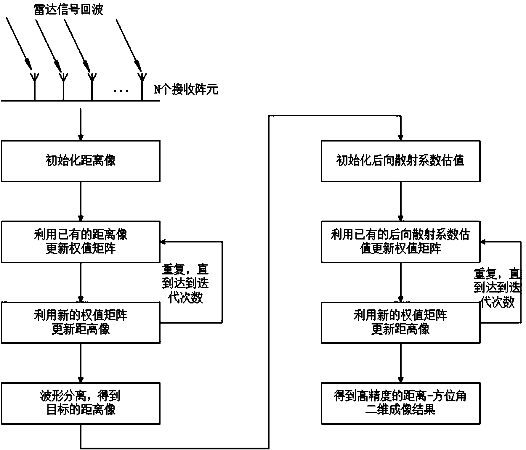
[0050] Such as figure 1 As shown, the MIMO radar range-angle two-dimensional super-resolution imaging algorithm of the present invention comprises the following steps:

[0051] Step 1: Establish a mathematical model of MIMO radar imaging;

[0052] Such as figure 1As shown in , the MIMO radar consists of M transmitting array elements and N receiving array elements, all of which are uniform linear arrays. The observation area satisfies the far-field condition and consists of L distance units and K angle units.

[0053] Assuming that the sampling length of the MIMO radar transmit waveform is P, the discrete form of the transmit signal of the mth transmit array element is defined as

[0054] S m =[s m (1) s m (2) … s m (P)] T , m=1, 2, ..., M (7)

[0055] The transmit signal matrix of the MIMO radar transmit array is S=[s 1 the s 2 … s M ], distance unit r l Azimuth θ k The target backscatter coefficient at is expressed as β(l,k), then the target echo signal receiv...


PUM


Abstract

The invention relates to a MIMO radar distance-angle two-dimensional super-resolution imaging algorithm. The algorithm comprises the following steps: step 1, establishing a mathematic model for MIMO radar imaging; step 2, performing pulse compression by use of a multi-waveform self-adaptive pulse compression method, obtaining a distance image of an observation scene, and realizing separation of emitted waveforms to obtain a receiving signal of a MIMO radar virtual array; and step 3, at a virtual array end, performing orientation focusing on echo signals of different distance units by use of a super-resolution space spectrum estimation algorithm to finish high-resolution distance-angle two-dimensional focusing imaging.

Description

technical field [0001] The invention relates to a MIMO radar range-angle two-dimensional super-resolution imaging algorithm. Background technique [0002] MIMO radar is a new type of radar system that appeared at the beginning of this century, and has attracted the attention of radar workers since it was proposed. MIMO radar uses multiple transmitting antennas to transmit orthogonal signals at the same time, and then separates the transmitting waveforms through matched filtering at the receiving end to form a virtual array with far more elements than the actual number of array elements, thus obtaining many advantages, such as more identifiable Number of targets, higher angular resolution, etc. The working mode of MIMO radar makes its imaging have the characteristics of real-time and high resolution, so MIMO radar imaging has broad application prospects. Designing a suitable imaging algorithm is the key to give full play to the advantages of MIMO radar imaging. [0003] A ...

Claims


Application Information

Patent Timeline
Patent Type & Authority Applications(China)
IPC IPC(8): G01S13/89
CPCG01S7/42G01S13/89
Inventor 王伟马跃华张斌梁栋李欣黄平王慧陈铮
Owner HARBIN ENG UNIV
Learn More