Full-automatic rough machining method and system for motorcycle wheel

A fully automatic and friction wheel technology, which is applied in metal processing, metal processing equipment, metal processing machinery parts, etc., can solve the problems of low processing accuracy, labor and labor, and low production efficiency, so as to improve production accuracy and reduce production cost, productivity improvement effect

Active Publication Date: 2014-09-03
ZHEJIANG WANFENG TECH DEV CO LTD
View PDF9 Cites 16 Cited by
  • Summary
  • Abstract
  • Description
  • Claims
  • Application Information

AI Technical Summary

Problems solved by technology

[0002] In the existing technology, the center hole and the valve hole need to be processed for the motorcycle wheel hub. At present, most manufacturers use semi-automatic processing, which requires a lot of manpower and labor.
Therefore, some companies have developed several types of fully automatic processing equipment for the processing needs of motorcycle wheels, such as the Chinese invention patent number "201220671796. As shown in the Chinese invention patent with the invention patent number "201220690383.6" and the patent name "Wheel Hub Drilling and Milling Integrated Machining Machine", in the actual production process, these devices still need to be equipped with production workers to assist in processing, and it is impossible to truly realize fully automated production. , and its production efficiency is low, and the processing accuracy is not high, so it is necessary to improve

Method used


Image

  • Full-automatic rough machining method and system for motorcycle wheel
  • Full-automatic rough machining method and system for motorcycle wheel
  • Full-automatic rough machining method and system for motorcycle wheel

Examples


Embodiment Construction

[0034] The following descriptions are only preferred embodiments of the present invention, and therefore do not limit the protection scope of the present invention.

[0035] Examples, see Figure 1 to Figure 6 as shown,

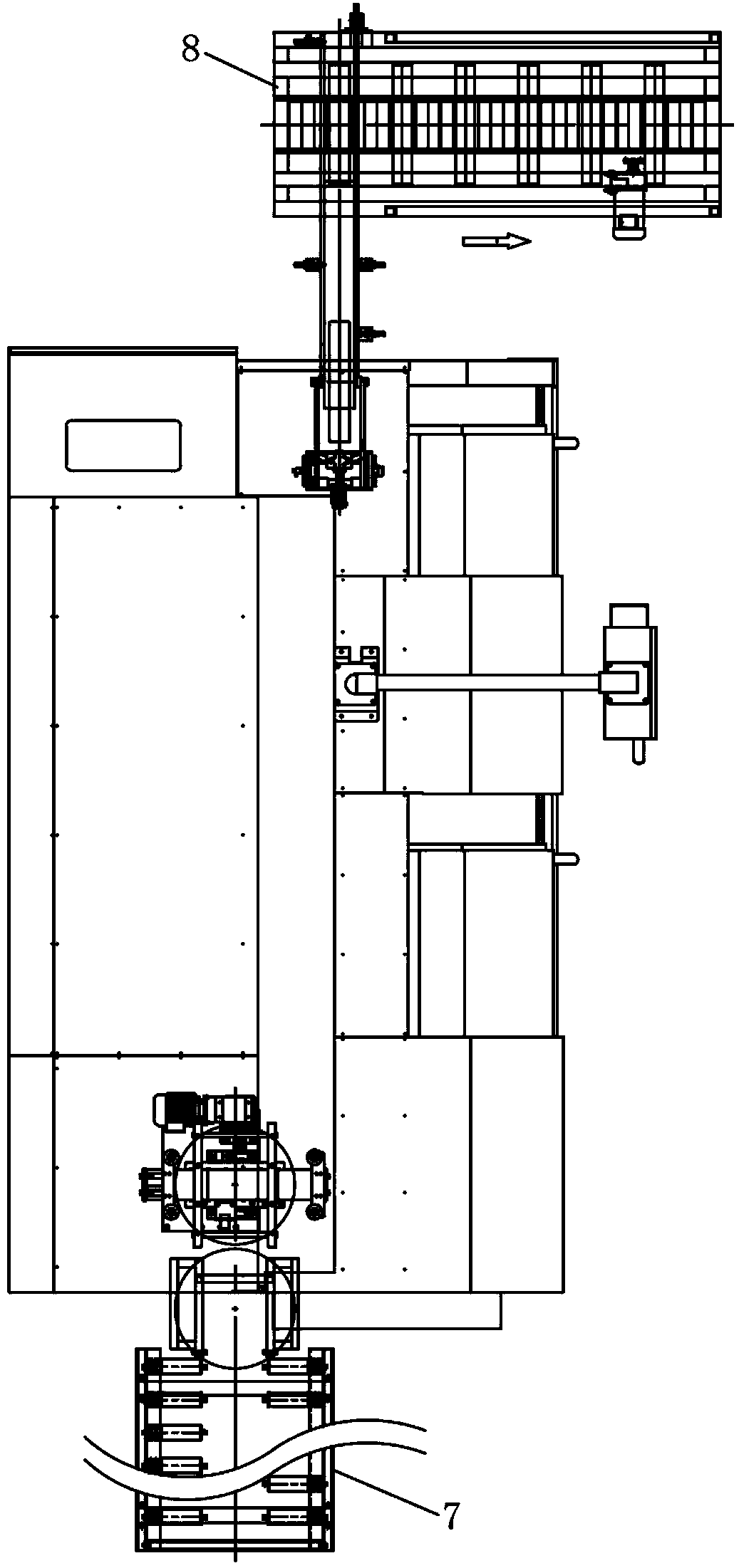
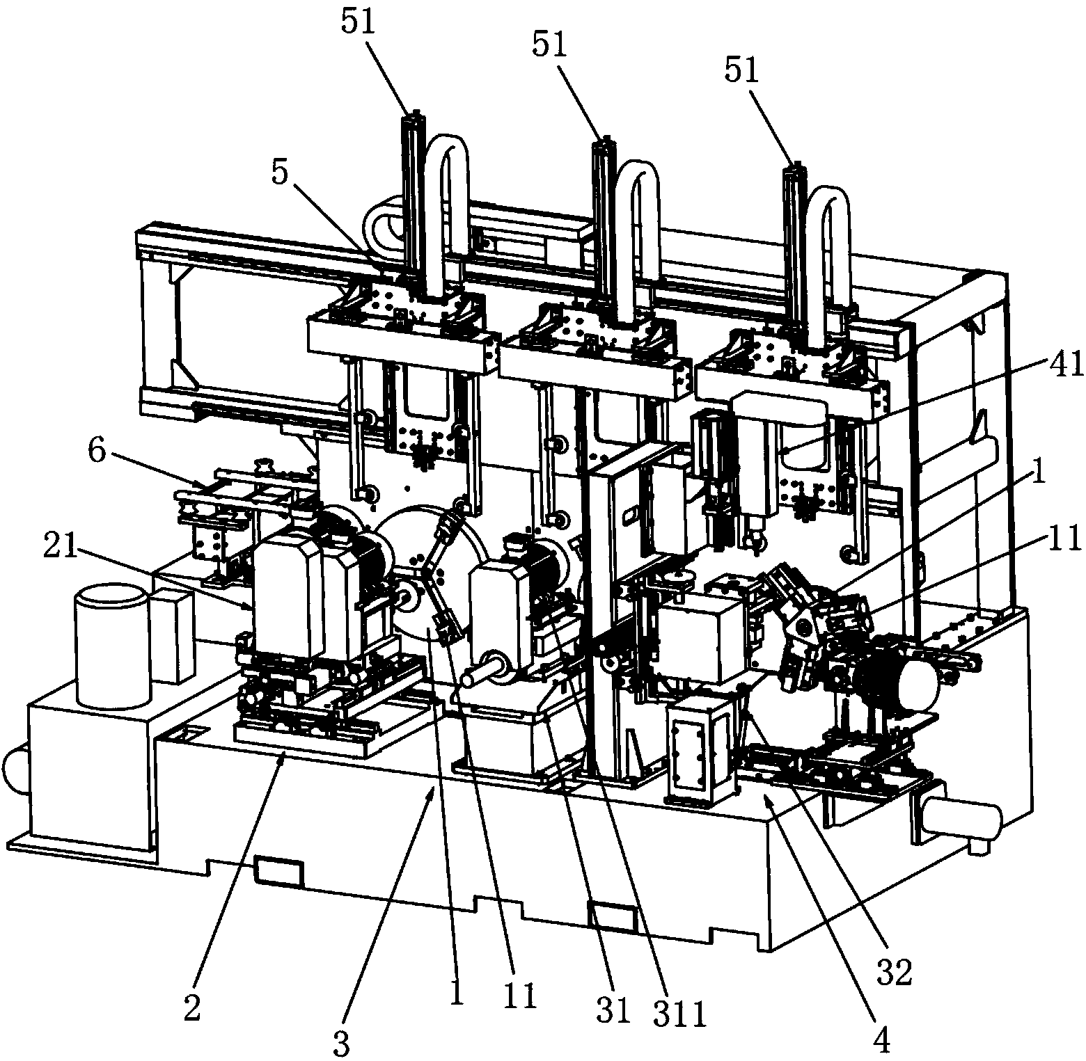
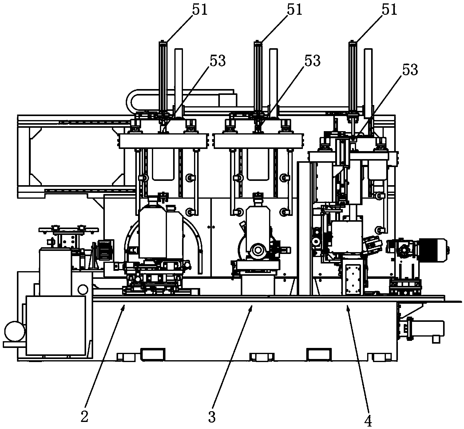
[0036] A method and system for fully automatic rough machining of a friction wheel, including a machine tool. The machine tool is sequentially provided with a cutting riser gate station 2, a drilling center hole station 3, and an air valve core hole drilling station 4 according to the feeding direction. There is a visual identification device for identifying the wheel hub model and an intelligent control system for adjusting the processing program by receiving the signal from the visual identification device. There are three synchronous claw discs 1 for synchronous operation, and the three claw discs 1 are respectively set at cutting riser gate station 2, drilling center hole station 3 and valve core hole drilling station 4, and the machine tool has three se...


PUM


Abstract

The invention discloses a full-automatic rough machining method and system for a motorcycle wheel. A machine tool is sequentially provided with a dead head and sprue cutting station, a center hole drilling station and a valve core hole drilling station in the feeding direction. The dead head and sprue cutting station, the center hole drilling station and the valve core hole drilling station in the feeding direction are respectively provided with a claw disc for three-station synchronous working. Each claw disc is provided with three synchronous pneumatic claws for clamping a hub. The synchronous pneumatic claws sequentially convey hub workblanks to the dead head sprue cutting station, the center hole drilling station and the valve core hole drilling station for continuous machining. A dead head and sprue cutting device at the dead head and sprue cutting station completes dead head cutting and sprue cutting of the third hub workblank at the same time, center hole drilling and valve core hole drilling are completed on the first and second hub workblanks conveyed to the center hole drilling station and the valve core hole drilling station respectively at the same time at the center hole drilling station and the valve core hole drilling station, and the machined hub workblanks are conveyed to a discharging assembly line. According to the full-automatic rough machining method and system for the motorcycle wheel, production efficiency and production precision can be greatly improved, and the production cost is reduced.

Description

technical field [0001] The invention relates to the technical field of automatic processing methods and equipment for motorcycle wheel hubs. Background technique [0002] In the prior art, the center hole and the valve hole need to be processed for the motorcycle wheel hub. At present, most of the production enterprises are doing semi-automatic processing, which requires a lot of manpower and effort. Therefore, some companies have developed several types of fully automatic processing equipment for the processing needs of motorcycle wheels, such as the Chinese invention patent number "201220671796. As shown in the Chinese invention patent with the invention patent number "201220690383.6" and the patent name "Wheel Hub Drilling and Milling Integrated Machining Machine", in the actual production process, these devices still need to be equipped with production workers to assist in processing, and it is impossible to truly realize fully automated production. , and its production...

Claims


Application Information

Patent Timeline
Patent Type & Authority Applications(China)
IPC IPC(8): B23P23/00B23Q7/00B23Q3/08B23Q11/00
CPCB23P23/00B23Q3/08B23Q7/04B23Q11/0042B23Q2703/04
Inventor 袁亮亮章旭霞陈炳锋吴军石鑫伟
Owner ZHEJIANG WANFENG TECH DEV CO LTD
Why Eureka
Try Eureka