
Ball head pressing and mounting equipment

A ball head and equipment technology, which is applied in metal processing equipment, workpiece clamping devices, metal processing, etc., can solve the problems of affecting the press-fitting efficiency and easy shaking of the operating rod, so as to achieve firm fixation, not easy to shake, and improve work efficiency Effect

Inactive Publication Date: 2014-09-03
SIP GOLDWAY TECH
View PDF6 Cites 11 Cited by
  • Summary
  • Abstract
  • Description
  • Claims
  • Application Information

AI Technical Summary

Problems solved by technology

In the prior art, the clamping part of the lower fixture is generally fixed on the lower half of the operating rod. Therefore, when the ball head is pressed, the operating rod is prone to shaking, which affects the press-fitting efficiency. There will be errors between them, and the clamping parts in the prior art cannot be fine-tuned according to these errors, so it will also affect the press-fitting efficiency

Method used


Image

  • Ball head pressing and mounting equipment
  • Ball head pressing and mounting equipment
  • Ball head pressing and mounting equipment

Examples


Embodiment Construction

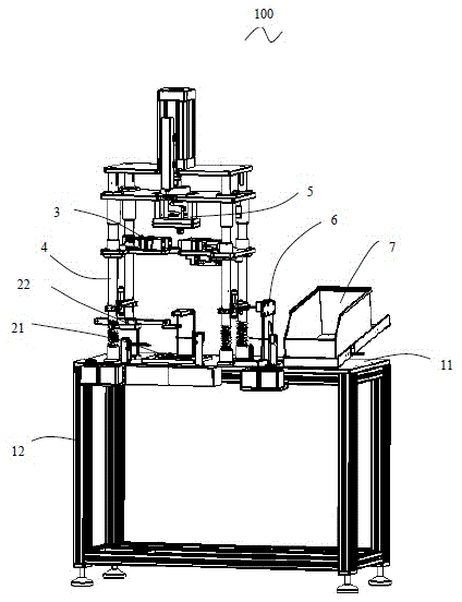
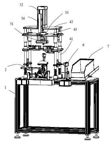
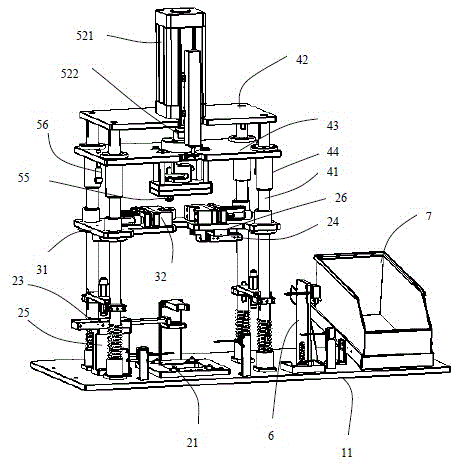
[0022] See Figure 1 to Figure 7 , the ball head press-fitting equipment 100 in an embodiment of the present invention includes a ball head 200 installed on the operating rod 301 of the workpiece 300, including a frame 1, a workpiece fixture 2, a travel frame 4, and a The ball clamp device 3 , the press-fitting device 5 arranged above the ball clamp device 3 , the workpiece detection device 6 for detecting the workpiece 300 , and the magazine device 7 for placing and storing components such as the ball tip 200 . The frame 1 includes a workbench 11 and a frame body 12 for supporting the workbench 11 . The workpiece fixture 2 , travel frame 4 , and workpiece detection device 6 are fixed on the workbench 11 . The pressing device 5 is arranged on the travel frame 4 and can move up and down along the travel frame 4 .

[0023] The workpiece fixture 2 includes a chassis clamp 21 for fixing a chassis 302 of the workpiece 300 and an operating rod clamp 22 for fixing an operating rod ...


PUM


Abstract

The invention relates to ball head pressing and mounting equipment which is used for mounting a ball head on an operating rod of a workpiece. The equipment comprises a work table, a stroke frame which is arranged on the work table, a workpiece clamp which is fixed on the work table and is used for fixing the workpiece, and a pressing and mounting device which is arranged on the stroke frame and can move up and down along the stroke frame, wherein the workpiece clamp comprises a first clamping element and a second clamping element which are relatively arranged to be used for crisscross clamping the operating rod of the workpiece; the first clamping element comprises a first piston cylinder, a first piston which is formed by outwards extension from the inside of the first piston cylinder, and a first clamping part which is arranged at the end part of the first piston to be used for clamping the operating rod; the second clamping element comprises a second piston cylinder, a second piston which is formed by outwards extension from the inside of the second piston cylinder, and a second clamping part which is arranged at the end part of the second piston to be used for clamping the operating rod; the first clamping part and the second clamping part are relative and are used for crisscross clamping the operating rod.

Description

technical field [0001] The invention relates to a ball head press-fitting device. Background technique [0002] The ball head press-fitting equipment is used to install the ball head on the operating rod of the workpiece, and it is a kind of equipment commonly used in the assembly equipment of auto parts at present. [0003] The current ball head press-fitting equipment includes a frame, a clamp set, a travel frame, and a pressing piece for pressing the ball head onto the operating rod. The frame includes a workbench and a frame for supporting the workbench. The clamp set includes a lower clamp fixed on the frame body and an upper clamp fixed on the travel frame. The upper clamp is used to fix the ball head. The lower clamp is used to fix the base of the base of the workpiece and the clamping piece extending upward from the base to fix the operating rod. The lower fixture generally forms different models according to different workpiece preparations. In the prior art, t...

Claims


Application Information

Patent Timeline
IPC IPC(8): B23P19/027
CPCB23P19/027B25B11/02
Inventor 李佳
Owner SIP GOLDWAY TECH
Learn More