
The Constant Force Feeding Device of the Subpackaged Shell

A sub-packed, artillery shell technology, applied in the direction of ammunition supply, weapon accessories, offensive equipment, etc., can solve the problems of constant sending elastic force, affecting shooting effect, inconsistent projectile sending position, etc., to achieve convenient operation and structure. Simple, mass-reducing effects

Inactive Publication Date: 2016-06-29
PEOPLES LIBERATION ARMY ORDNANCE ENG COLLEGE
View PDF5 Cites 0 Cited by
  • Summary
  • Abstract
  • Description
  • Claims
  • Application Information

AI Technical Summary

Problems solved by technology

Especially for a sub-package artillery with a certain degree of wear and tear on the inner bore of the barrel, a small difference in the delivery force will cause a large change in the position of the projectile, thereby affecting the initial flight velocity of the projectile
[0003] In the prior art, the loading process before the launch of the projectile is all manually completed by the delivery hand, which is difficult to ensure that the elastic force of different delivery hands or even the same delivery hand is constant during each loading process. The inconsistency of the delivery force will lead to the inconsistency of the delivery position of each projectile, which will affect the initial flight velocity of the projectile and the spread of the projectile, and finally affect the shooting effect

Method used


Image

  • The Constant Force Feeding Device of the Subpackaged Shell
  • The Constant Force Feeding Device of the Subpackaged Shell
  • The Constant Force Feeding Device of the Subpackaged Shell

Examples


Embodiment

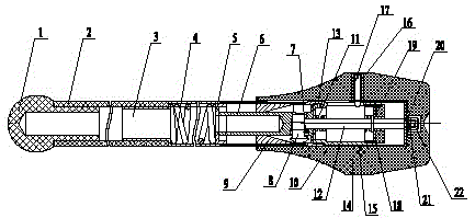
[0032] This embodiment is a constant force delivery device for sub-package shells, refer to figure 1 ,it includes:

[0033] (1) Force application mechanism

[0034] The force application mechanism is used for external personnel to directly apply thrust. The force application mechanism in this embodiment includes a force application head 1 and a hollow rod 2. For the convenience of operation, the force application head 1 in this embodiment is as follows: figure 1 The arrangement shown is in the form of a ball head, and the force application head 1 is provided with an extension rod, which is placed in the cavity of the hollow rod 2 and is interference-fitted with the inner cavity of the hollow rod 2 .

[0035] (2) elastic mechanism

[0036] The elastic force mechanism generates compressed elastic force under the action of external personnel's thrust, and this embodiment utilizes the compressed elastic force to push the projectile into place.

[0037] Such as figure 1 As show...


PUM


Abstract

The invention discloses a constant-force shell delivery device for split-charged shells. The constant-force shell delivery device comprises a force applying mechanism, an elastic force mechanism and a force release mechanism, wherein the force applying mechanism is used for externally applying thrust force, the elastic force mechanism is used for generating compression elastic force under the action of the external thrust force, and the force release mechanism is used for releasing the constant elastic force of compression so as to push a shell to move. The free end of the force applying mechanism is a force applying end used for externally applying thrust force, the non-free end of the force applying mechanism is connected with the non-free end of the force release mechanism through the elastic force mechanism, and the free end of the force release mechanism is pressed against the rear end face of a shell. The constant-force shell delivery device is simple in structure and free of magnitude of thrust force of an ammunition carrier; every time a shell is charged, the shell can be pushed in place at constant shell delivery force, and initial velocity dispersion caused by inconsistent shell delivery force can be eliminated; the magnitude of the shell delivery force can be adjusted in a stepless mode according to different requirements for physique of ammunition carriers, and thus the constant-force shell delivery device can be widely applied. The constant-force shell delivery device is suitable for charging split-charged shells.

Description

technical field [0001] The invention belongs to the field of military facilities, and relates to artillery launch and filling technology, in particular to a constant-force bomb feeding device for subpackaged artillery shells. Background technique [0002] At present, the artillery of the whole army is studying the important issues of "first hit" and "first group coverage" of artillery. For split artillery, projectile dispersion is the main factor affecting the above requirements, and the impact of projectile dispersion is The main factor is the muzzle velocity dispersion. A large number of experimental data show that, apart from the factors of the ammunition and the gun itself, the main reason for the muzzle velocity dispersion is that the delivery position of each projectile before firing cannot be completely consistent. The position of sending bullets in place is directly related to the size of the elastic force. Especially for a sub-package artillery with a certain wear ...

Claims


Application Information

Patent Timeline
Patent Type & Authority Patents(China)
IPC IPC(8): F41A9/38
Inventor 邓士杰靳秀文栾军英王平于贵波
Owner PEOPLES LIBERATION ARMY ORDNANCE ENG COLLEGE
Learn More