
Projector and supporting structure thereof

a technology of supporting structure and projector, which is applied in the field of projector and supporting structure, can solve the problems of easy to function supporting structure, difficult to adjust the length of the feet, and imminent problem of how to develop a supporting structure which is small in size, and achieves constant elastic force and adjusts the supporting structure easily and quickly.

Inactive Publication Date: 2007-10-04
BENQ CORP
View PDF4 Cites 3 Cited by
  • Summary
  • Abstract
  • Description
  • Claims
  • Application Information

AI Technical Summary

Benefits of technology

[0009]The invention is directed to a projector and a supporting structure thereof. As the deformation of an elastic element results in a substantially constant elastic force, the user can easily and quickly adjust the supporting structure to change the elevational angle and the horizon of the main body.

Problems solved by technology

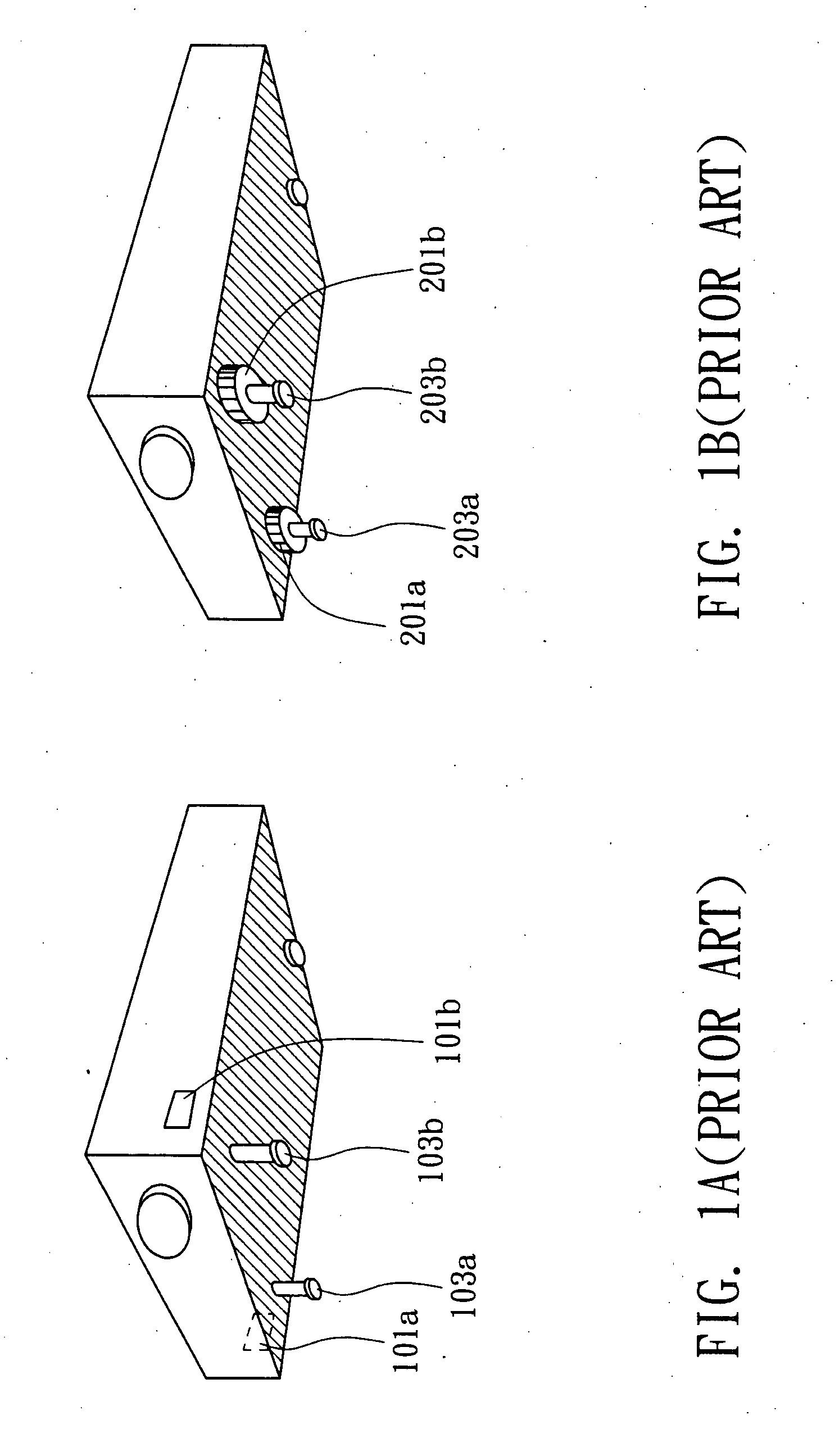
However, in the course of adjustment, the user has to hold the projector 100 by two hands all the time, which is very demanding and makes it difficult to adjust the lengths of the feet 103a and 103b.
Apart from the projector, various devices or articles with an adjustable supporting structure also have the same problem.
Therefore, how to develop a supporting structure which is easy to function and small in size has become an imminent issue to be resolved.

Method used


Image

  • Projector and supporting structure thereof
  • Projector and supporting structure thereof
  • Projector and supporting structure thereof

Examples


first embodiment

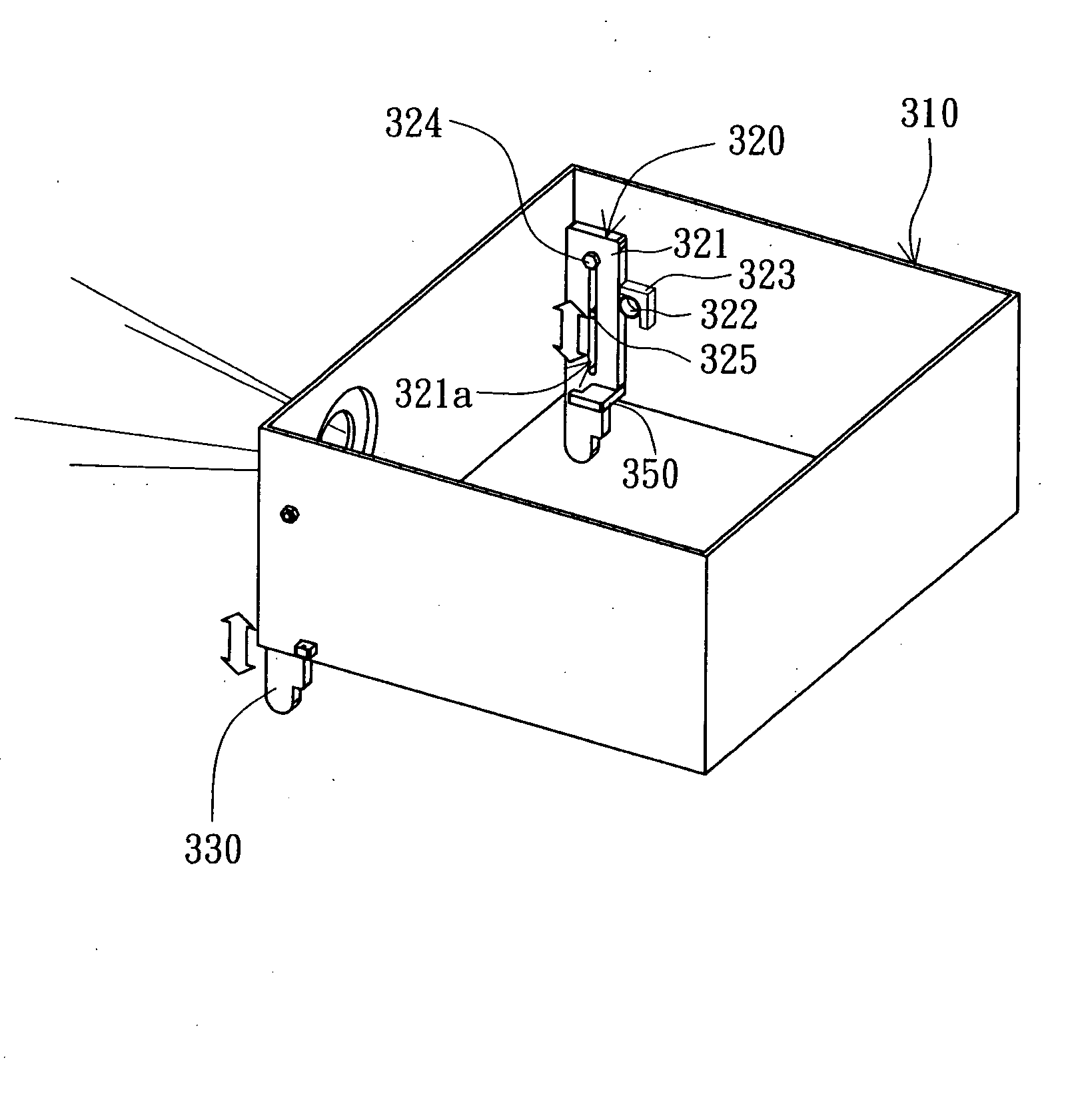
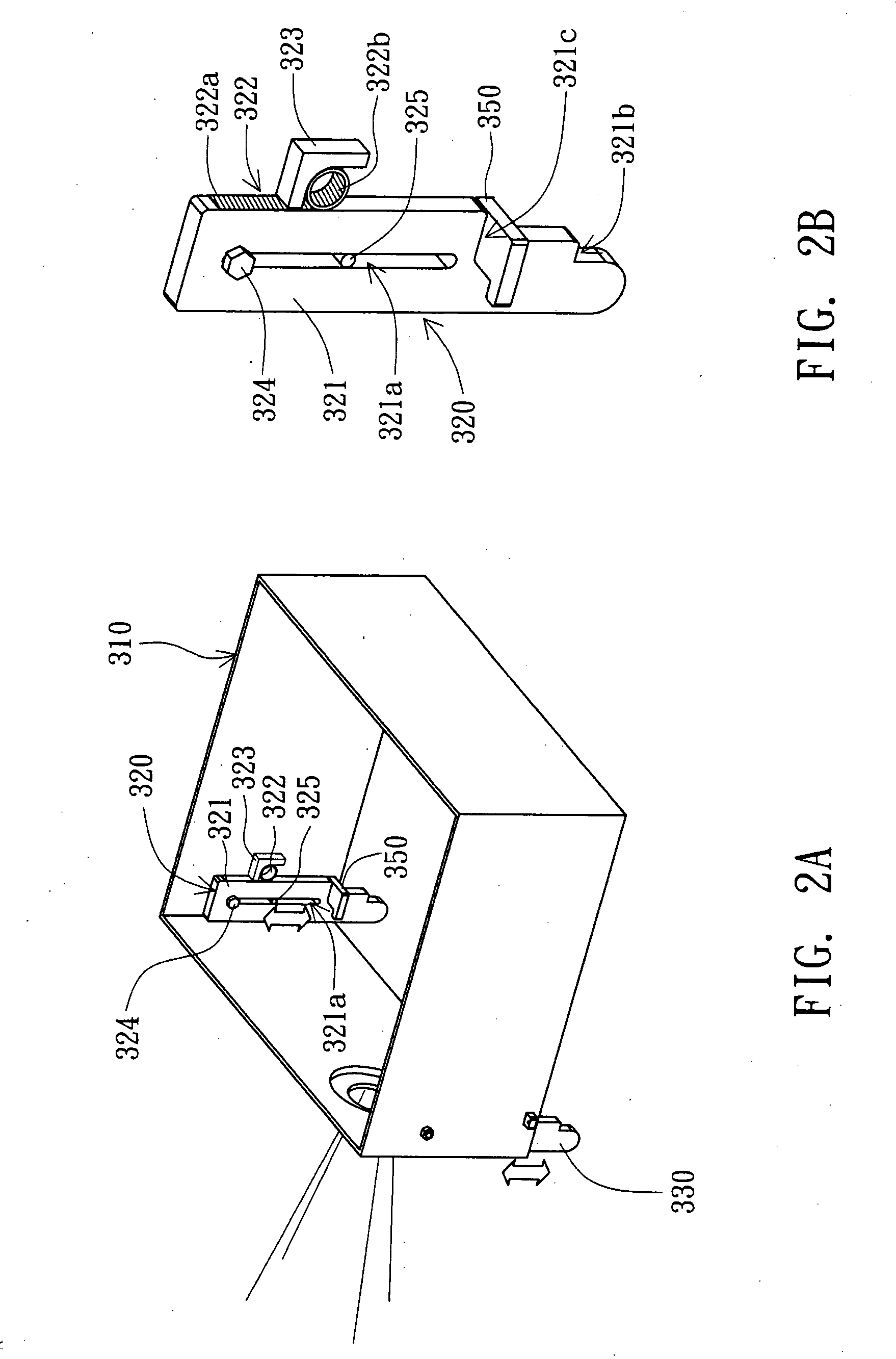
[0021]Referring to FIG. 2A, a perspective of a projector according to a first embodiment of the invention is shown. The projector 300 includes a main body 310 and at least a supporting structure. In the present embodiment of the invention, the supporting structure is exemplified by a supporting structure 320 and a supporting structure 330. The supporting structure 320 is disposed on an inner surface of a sidewall of the main body 310 and projected from the bottom of the main body 310. The supporting structure 330 is disposed on an inner surface of the other sidewall of the main body 310 and projected from the bottom of the main body 310. The two supporting structures 320 and 330 are respectively disposed at two opposite sides of the main body 310. The user can adjust the elevational angle and the horizon of the main body 310 by adjusting the lengths of the supporting structures 320 and 330. Despite the projector 300 of the present embodiment of the invention is exemplified by two ad...

second embodiment

[0030]Referring to both FIG. 3 and FIG. 4. FIG. 3 is a perspective of a projector according to a second embodiment of the invention. FIG. 4 is a side view of a supporting structure of FIG. 3. The projector 400 of the present embodiment of the invention differs with the projector 300 of the first embodiment in the fixing element 423 and the guiding bump 425 and the disposition of the supporting structures 420 and 430. As for other similarities, the same reference numbers are used and are not repeated here. As the supporting structure 420 and the supporting structure 430 have the same structure, the following elaboration is exemplified by the supporting structure 420 only.

[0031]The supporting structure 420 is disposed on an outer surface of a sidewall of the main body 310. The fixing element 423 retains the sliding element 321 and the elastic element 322 by enveloping the sliding element 321 as indicated in FIG. 4. Moreover, the guiding bump 425 is a screw inserted into a sliding slot...


PUM


Abstract

A projector and a supporting structure thereof are provided. The projector includes a main body and a supporting structure. The supporting structure is disposed at the main body. The supporting structure includes a sliding element and an elastic element. The sliding element is supported on a plane and can move backward and forward with respect to the main body. The elastic element has a first end and a second end. The first end is coupled to the sliding element, and the second end is coupled to the main body. The elastic element generates a substantially constant elastic force when the elastic element is deformed. As the sliding element moves with respect to the main body, the elastic force balances against the gravity force of the main body, such that the elevational angle of the main body with respect to the plane is changed.

Description

[0001]This application claims the benefit of Taiwan application Serial No. 095111679, filed Mar. 31, 2006, the subject matter of which is incorporated herein by reference.BACKGROUND OF THE INVENTION[0002]1. Field of the Invention[0003]The invention relates in general to a projector and a supporting structure, and more particularly to a projector and a supporting structure thereof capable of adjusting the elevational angle and the horizon of the main body with respect to the desk.[0004]2. Description of the Related Art[0005]Projectors have now been widely used in conference room, laboratory and families. It is a common experience to projector users that the frame may be inclined, too high or too low when projected on a screen. To solve this problem, the user has to adjust the horizon of the projector to avoid inclination and adjust the elevational angle of the projector with respect to the desk to avoid the frame being too high or too low.[0006]Referring to FIG. 1A, a perspective of ...

Claims


Application Information

Patent Timeline
Patent Type & Authority Applications(United States)
IPC IPC(8): G03B21/14
CPCG03B35/14G03B21/145
Inventor YIN, CHUN-HSIUNGLIN, YI-YENPAN, JIUNG-CHENGHSU, YI-TING
Owner BENQ CORP
Learn More