
Multi-vibrator based mutual vibration type vortex-induced vibration generation device

A power generation device, vortex-induced vibration technology, applied in the direction of engine components, machines/engines, mechanical equipment, etc., can solve the problems of reducing the engineering economy and practicability of VIVACE vortex-induced vibration power generation device, unfavorable online circulation, poor vibration consistency, etc. , to achieve good economic applicability, ensure power generation quality, and reduce manufacturing and installation costs.

Active Publication Date: 2014-08-27
THE FRONTIER TECH RES INST OF TIANJIN UNIV
View PDF9 Cites 13 Cited by
  • Summary
  • Abstract
  • Description
  • Claims
  • Application Information

AI Technical Summary

Problems solved by technology

However, the VIVACE device has significant defects: the VIVACE vortex-induced vibration power generation device uses a single vibrator to vibrate to generate power, and the vibrators are independent of each other, so each vibrator must be equipped with a set of transmission, power generation, power transmission and frequency conversion equipment; at the same time, due to poor vibration consistency , leading to high cost of frequency conversion, which is not conducive to Internet circulation
According to the existing research results, for low-speed water flow (flow rate not exceeding 2m / s), the diameter of VIVACE's vibrator should not exceed 10cm, and the length should not exceed 1m, so the maximum theoretical power generated by one vibrator is only 90W
Then, for a 360MW power plant, it needs to be equipped with transmission, power generation and frequency conversion equipment to reach 4×10 6 It is obviously not economical or practical to manufacture so many generators in actual engineering
It can be seen that the above defects greatly reduce the engineering economy and practicability of the VIVACE vortex-induced vibration power generation device

Method used


Image

  • Multi-vibrator based mutual vibration type vortex-induced vibration generation device
  • Multi-vibrator based mutual vibration type vortex-induced vibration generation device
  • Multi-vibrator based mutual vibration type vortex-induced vibration generation device

Examples


Embodiment

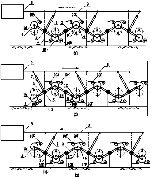
[0018] A counter-vibration vortex-induced vibration power generation device based on multiple vibrators, such as figure 1 , 2 As shown, it consists of a vibrator 1, a support rod 2, a connecting rod 3, a bearing 4, a torsion spring 5, a linear guide rail 6, a lower transmission rod 7, an upper transmission rod 8 and a linear generator 9, and the support rod 2 is fixed at the bottom of the water flow; The middle part of the connecting rod 3 is hinged with the top of the support rod 2 through the bearing 4, the middle part of the connecting rod 3 is provided with a torsion spring 5, and the torsion spring is located outside the bearing. The vibrator 1, the middle part of the connecting rod 3 is fixedly connected to the bottom of the lower transmission rod 7; the top of the lower transmission rod 7 is provided with a linear guide rail 6, and the outer end of the linear guide rail 6 is connected to the upper transmission rod 8 through a bearing 4; every other pair of vibrators in ...


PUM


Abstract

A multi-vibrator based mutual vibration type vortex-induced vibration generation device which comprises vibrators, support rods, connecting rods, bearings, torsion springs, linear guide rails, lower transmission rods, an upper transmission rod and a linear generator is disclosed. Each support rod is fixed at the bottom of water flow; the middle part of each connecting rod is hinged to the top of each support rod through each bearing; the middle part of each connecting rod where each torsion spring is arranged is fixed at the outside of each bearing; the two ends of each connecting rod are connected to each linear guide rail respectively; the outer ends of the linear guide rails are connected to the vibrators respectively; the bottom of each lower transmission rod is fixedly connected to the middle part of each connecting rod, and each linear guide rail is arranged on the top of each lower transmission rod; the upper transmission rod is connected to each lower transmission rod through each bearing to constitute an integral vibration system; the upper transmission rod is connected to the linear generator. The advantages of the multi-vibrator based mutual vibration type vortex-induced vibration generation device are that the device realizes uniform energy collection of the multiple vibrators, improves generation efficiency of vibrator group, reduces manufacturing and installation cost and improves engineering practicability as a large number of low-capacity generators are replaced by a small number of high-capacity generators, and is simple in structure as well as easy to implement.

Description

technical field [0001] The invention relates to the fields of fluid mechanics and new energy power generation, in particular to a counter-vibration vortex-induced vibration power generation device based on multiple vibrators. Background technique [0002] In recent years, energy storage has become a key issue affecting the development of various countries. As a result, the development and utilization of new energy sources has become a hot topic in energy development in various countries. Among many new energy types, ocean current energy is favored by energy developers from all over the world due to its advantages such as large scale, wide distribution, and abundant reserves. According to statistics, the world's available ocean current energy is as high as 5×10 6 MW. In my country, the theoretical exploitable volume of coastal current alone can reach 1.4×10 5 MW is equivalent to the installed capacity of 70 Three Gorges hydropower stations, which shows its huge reserves....

Claims


Application Information

Patent Timeline
Patent Type & Authority Applications(China)
IPC IPC(8): F03B13/00
Inventor 燕翔练继建张军卜同胜刘卓刘昉
Owner THE FRONTIER TECH RES INST OF TIANJIN UNIV
Learn More