Floor connecting structure

A floor and body technology, applied in the direction of building structure, floor, building, etc., can solve the problems of complicated floor connection and unreliable connection, and achieve the effect of simple connection, firm and reliable connection, and cost saving.

Inactive Publication Date: 2014-08-27
ANHUI YIJIAXIN WOOD
View PDF10 Cites 0 Cited by
  • Summary
  • Abstract
  • Description
  • Claims
  • Application Information

AI Technical Summary

Problems solved by technology

[0004] The technical problem to be solved by the present invention is to provide a floor joint structure, which makes the floor joint not only simple but also reliable, so as to overcome the defects of complicated and unreliable floor joints in the prior art

Method used


Image

  • Floor connecting structure
  • Floor connecting structure

Examples


Embodiment Construction

[0013] The present invention will be further described below in conjunction with the accompanying drawings and embodiments.

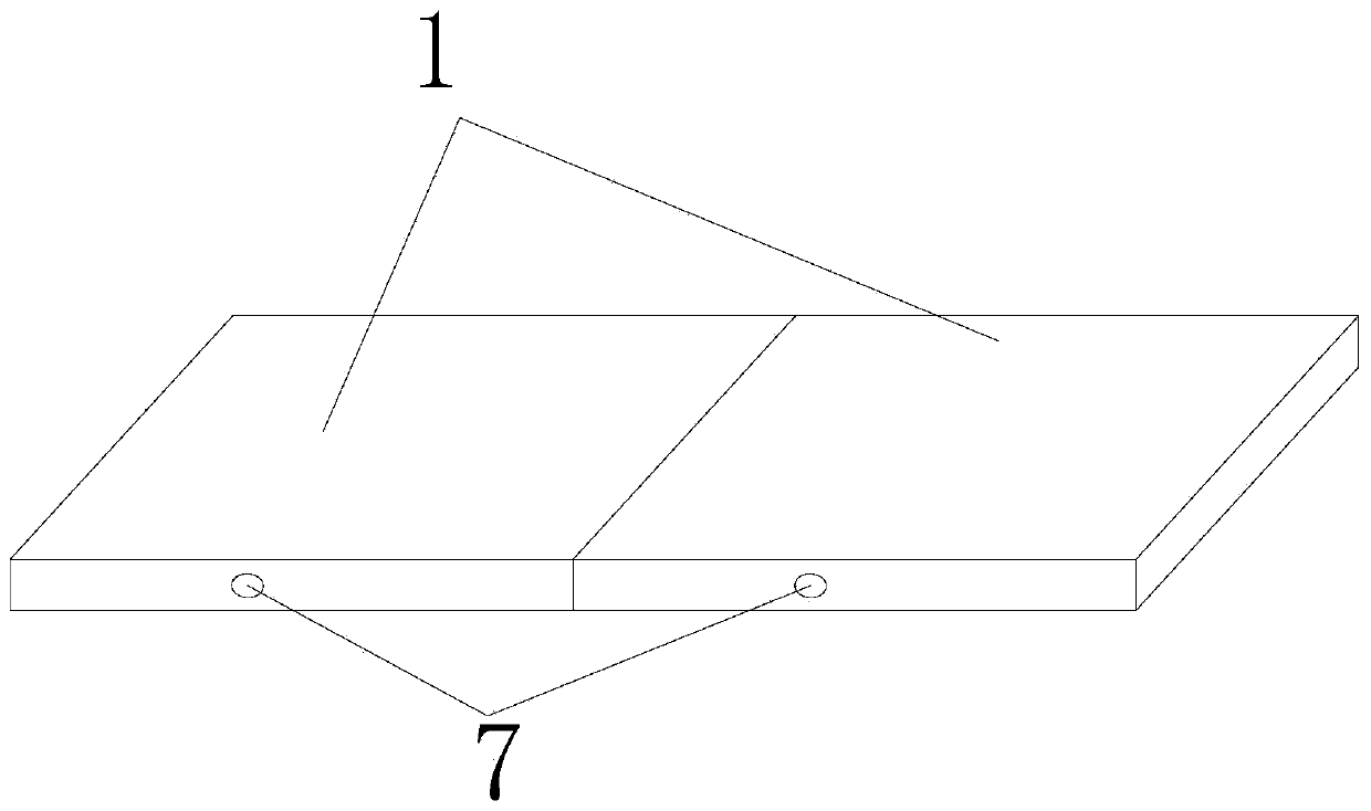
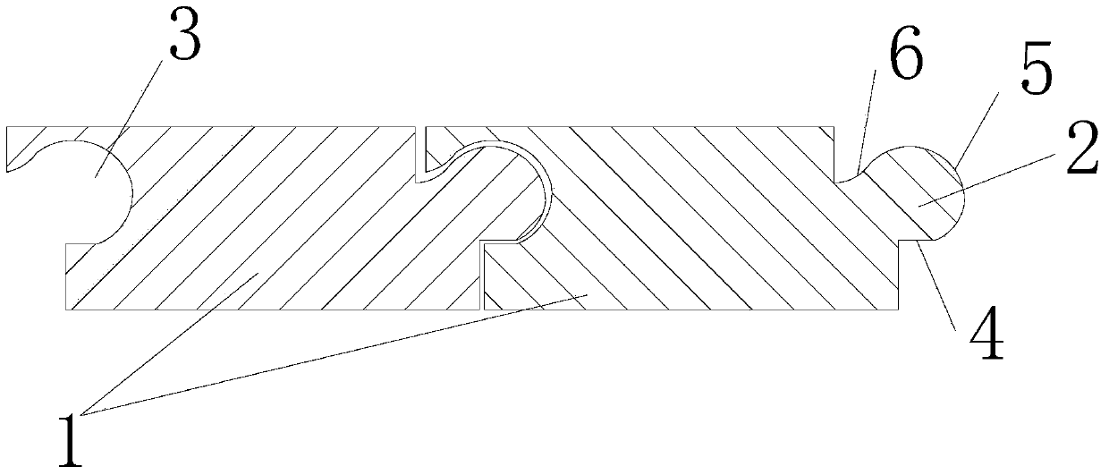
[0014] figure 1 It is a structural schematic diagram of an embodiment of the present invention; figure 2 yes figure 1 cutaway view.

[0015] Such as figure 1 and figure 2 As shown, a preferred floor joint structure of the present invention includes: a floor body 1, the two ends of the floor body 1 in the width direction are respectively provided with an engagement protrusion 2 and an engagement groove 3, and the engagement protrusion 2 and the engagement groove 3 The shapes of the floor plates are matched with each other, and the joint of the floor is realized through the cooperation of the joint protrusion 2 and the joint groove 3 .

[0016] The engaging protrusion 2 includes a reference segment 4 , a positioning segment 5 and an anti-slip segment 6 .

[0017] Specifically, the reference section 4 is located at the lower end of the floor body 1...


PUM

PropertyMeasurementUnit
Slopeaaaaaaaaaa

Abstract

The invention discloses a floor connecting structure which comprises floor bodies. The two ends of each floor body in the width direction are provided with a connecting protrusion and a connecting groove respectively, and the connecting protrusions are matched with the connecting grooves in shape. Each connecting protrusion comprises a reference section, a positioning section and an anti-slip section. The reference sections are located at the lower ends of the floor bodies and serve as connecting references. The anti-slip sections are located at the upper ends of the floor bodies and used for preventing the positioning sections from slipping off from the connecting grooves. The positioning sections are located at the middle ends of the floor bodies and enable the reference sections to be connected with the anti-slip sections. According to the floor connecting structure, floors are connected by using matching of the connecting protrusions and the connecting grooves at the two ends of the floors in the width direction, the connecting protrusions comprise the reference sections, the positioning sections and the anti-slip sections, connection of the floors is made to be simpler due to arrangement of the reference sections, and connection of the floors is made to be firmer and more reliable due to arrangement of the anti-slip sections; in addition, the floors are made into inclined floors, material losses are reduced, and the cost is saved.

Description

technical field [0001] The invention relates to the technical field of interior decoration, in particular to a floor connecting structure. Background technique [0002] With the rapid development of the modern economy, more and more people use the floor to decorate the ground. The floor also brings cleanliness and comfort to people while being favored. Adhesives are often used in traditional floor splicing techniques. During use, the adhesives will dissolve when heated, affecting the degree of connection between adjacent floors. Later, a positioning fit connection method appeared, but there are defects such as complicated and unreliable connections. . [0003] Therefore, it is necessary to provide a floor connecting structure, which makes the floor connecting simple and reliable, so as to overcome the above-mentioned technical defects. Contents of the invention [0004] The technical problem to be solved by the present invention is to provide a floor joint structure, whi...

Claims


Application Information

Patent Timeline
IPC IPC(8): E04F15/02
Inventor 吴永志
Owner ANHUI YIJIAXIN WOOD
Why Eureka
Try Eureka