Wet rotor motor pump

A technology of motor pump and rotor, applied in the field of wet rotor motor pump

Active Publication Date: 2017-11-17
WILO SE
View PDF1 Cites 0 Cited by
  • Summary
  • Abstract
  • Description
  • Claims
  • Application Information

AI Technical Summary

Problems solved by technology

A significant disadvantage of these solutions is that the flow through the rotor space changes depending on the operating point of the pump

Method used


Image

  • Wet rotor motor pump

Examples


Embodiment Construction

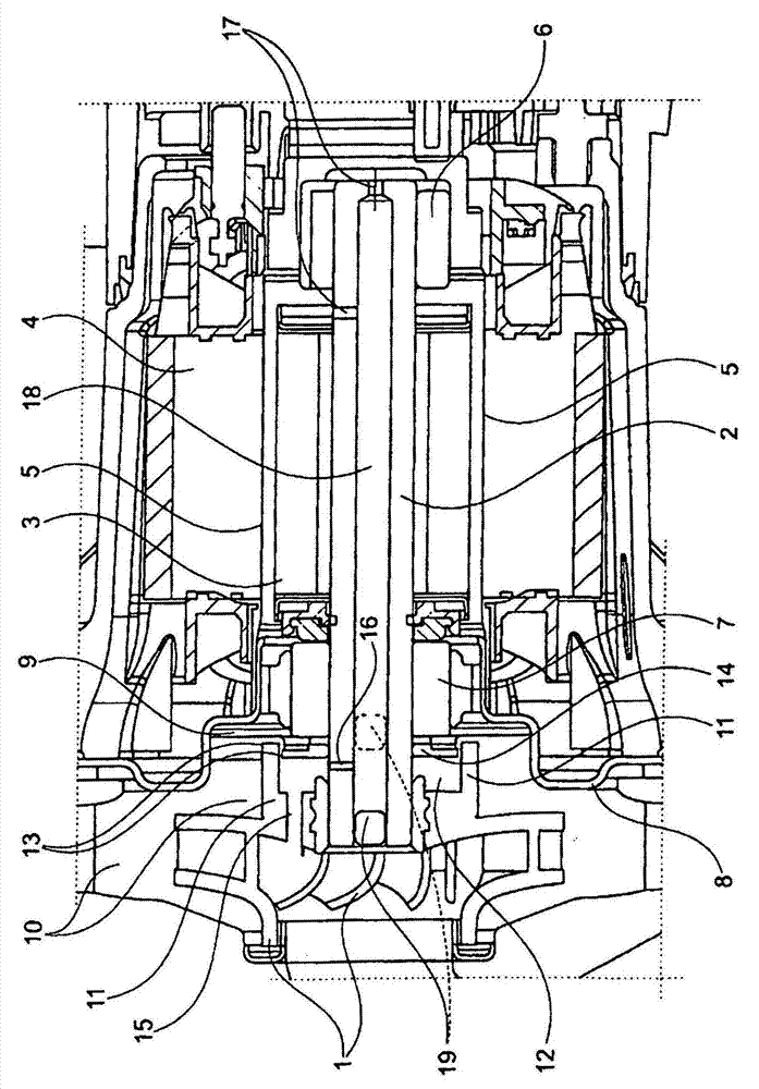
[0016] The wet rotor motor pump has, as a rotary pump, an impeller 1 driven by a coaxial hollow shaft 2 which supports a rotor assembly 3 which rotates in a stator 4 of the electric motor. The rotor assembly 3 is separated from the stator by a gap tube 5 through which the conveyed medium flows so that the bearings 6 , 7 located in the gap tube 5 are lubricated and cooled. The gap tube is closed at the rear, so that it can also be called a "gap pot".

[0017] At the end of the gap tube 5 facing the impeller, a gap tube flange 8 is formed, against which an annular separating wall 9 in the form of a sheet metal part rests in order to separate the pump chamber 10 from the interior of the gap tube 5 . At least one throughflow opening is located in the partition wall 9 , whereby the conveying medium reaches the interior of the gap tube 5 .

[0018] On the rear side of the pump impeller 1 , an annular projection 11 is integrally formed coaxially, so that an annular space 12 is form...


PUM


Abstract

The invention relates to a wet-rotor motor pump comprising a can which separates the stator from the motor shaft that is mounted in the can and carries rotor laminations, said motor shaft projecting into the pump chamber and carrying, in said pump chamber, the impeller. A coaxial annular space is provided between a separating wall separating the can interior from the pump chamber and the rear of the impeller, the pumped liquid flowing from the annular space into the rotor space surrounded by the can through at least one flow passage in the separating wall, and flowing back to the pump chamber once it has permeated the rotor space, especially through the longitudinal hollow space of the motor shaft. The rear of the impeller has a coaxial annular projection that separates the rear annular space surrounding the motor shaft from the rest of the pump chamber, apart from at least one throttle gap extending through the annular projection. Pumped liquid flows from the pump pressure side into the annular space through the throttle gap in a throttled manner, said annular space being connected to the pump intake side by at least one throttled opening in the rear wall of the impeller and / or in the wall of the hollow shaft of the motor.

Description

technical field [0001] The invention relates to a wet rotor motor pump comprising a gap tube which separates the motor stator from a motor shaft supported in the gap tube which carries the rotor set, which protrudes into the pump chamber and there Support pump impeller. Background technique [0002] A typical heating circulation pump consists of the following main components: a drive motor, a pump casing and an impeller. The motor is usually an electric motor designed for wet operation. The impeller is often a radial impeller and transmits the power of the motor to the medium. In these wet rotary lobe pumps, the rotor of the electric motor is flushed by the medium. The stator is separated from the medium by a gap tube / gap pot. The bearings of the rotor are lubricated by the medium. Such a structure requires no maintenance and has a very long service life if the media is relatively clean. To ensure that a flow through the rotor space takes place, the pressure difference...

Claims


Application Information

Patent Timeline
Patent Type & Authority Patents(China)
IPC IPC(8): F04D13/06F04D29/16
CPCF04D13/0613F04D29/167F05D2240/61
Inventor G·施特雷洛
Owner WILO SE
Why Eureka
Try Eureka