
Virtual automatic control experimental system and design method of virtual automatic control experimental system

An experimental system and experimental technology, applied in general control systems, control/regulation systems, simulators, etc., can solve problems such as unsmooth serial communication between hardware and software, aging of hardware experimental equipment, and large impact on experimental results. Achieve the effects of powerful image processing and display functions, convenient self-learning, and convenient operation

Inactive Publication Date: 2014-08-20
NORTHWEST UNIV(CN)
View PDF5 Cites 6 Cited by
  • Summary
  • Abstract
  • Description
  • Claims
  • Application Information

AI Technical Summary

Problems solved by technology

[0002] The software and hardware composition of the existing automatic control experiment system has disadvantages such as aging hardware experiment equipment is not easy to update, the quantity is limited, the experiment content is not flexible, the serial communication between hardware and software is not smooth, and the experiment results are greatly affected by the state of the hardware equipment.

Method used


Image

  • Virtual automatic control experimental system and design method of virtual automatic control experimental system
  • Virtual automatic control experimental system and design method of virtual automatic control experimental system
  • Virtual automatic control experimental system and design method of virtual automatic control experimental system

Examples


Embodiment 1

[0057] If the closed-loop transfer function of the second-order system is selected in the experiment Compare it with the standard second-order system closed-loop transfer function In comparison, it can be obtained that the damping ratio of the second-order system is 0.4, and the natural oscillation angular frequency is 5rad / s. The time-domain analysis of this second-order system can be carried out as follows:

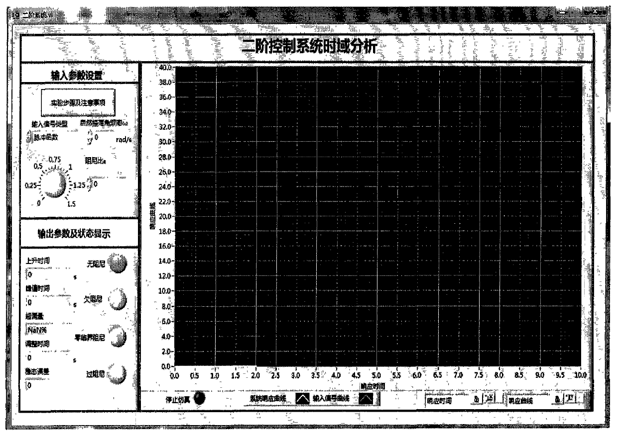
[0058] Step 1. Open the virtual automatic control experiment system, select the second-order system in the menu bar, the interface is as follows figure 2 ;

[0059] Step 2. In the "Input Parameter Settings" module, click the "Experimental Steps and Precautions" button, and the front panel of the experimental steps will pop up for the experimenter to read, such as image 3 , after mastering the experimental steps and precautions, the experimenter can conduct system time-domain analysis under the action of various typical signals;

[0060] Step 3. There is an "Inpu...

Embodiment 2

[0067] If the open-loop transfer function is selected in the experiment: The root locus analysis of the fifth-order system can be carried out as follows:

[0068] 1. Open the virtual automatic control experiment system, select "root locus analysis" in the menu bar, the interface is as follows Figure 9 .

[0069] 2. Input the coefficients of the open-loop transfer function in the "numerator polynomial" and "denominator polynomial" modules. Since the root locus draws the distribution of closed-loop characteristic roots when a certain parameter of the open loop changes, this system takes the open-loop gain K as Change parameters, default K=1.

[0070] 3. Some characteristics and parameters of the root locus analysis are recorded in the experimental parameter module, including the number of the root locus, the number of asymptotes, the separation point and meeting point of the root locus, the intersection point of the asymptote and the real axis, The starting and ending angle...

Embodiment 3

[0074] If the oscillation link in the typical link is selected as the research object in the experiment, the time constant of the oscillation link is T = 1s, and the damping ratio ξ = 0.5. The frequency domain analysis of this typical link can be carried out according to the following steps:

[0075] 1. Open the virtual automatic control experiment system, select typical link analysis in the menu bar, the interface is as follows Figure 10 ;

[0076] 2. In the "Parameter Setting" module, click the "Experimental Procedures and Precautions" button, and the front panel of the experimental procedure will pop up for the experimenter to read. After mastering the experimental procedure and precautions, the experimenter can carry out various typical procedures. Frequency domain analysis;

[0077] 3. There is a button of "typical link type" in the "parameter setting" module, through which the experimenter can select a typical link. Typical links in frequency domain analysis include a...


PUM


Abstract

The invention discloses a virtual automatic control experimental system and a design method of the virtual automatic control experimental system. The virtual automatic control experimental system comprises a time domain analysis method experiment module, a root-locus method experiment module, a frequency domain analysis method experiment module, a system correction experiment module and an open experiment module, wherein the time domain analysis method experiment module comprises a first-order system time domain analysis module, a second-order system time domain analysis module and a high-order system time domain analysis module; the root-locus method experiment module comprises a second-order system root-locus analysis module, a third-order system root-locus analysis module and a high-order system root-locus analysis module; the frequency domain analysis method experiment module comprises a typical link frequency response characteristic analysis module and a composite system frequency response analysis module; the system correction experiment module comprises a series connection lead correction module, a series connection lag correction module, a series connection lag-lead correction module and a PID correction module; the open experiment module comprises a water level control module, an elevator control module and a traffic lamp control module. By means of the virtual automatic control experimental system and the design method, a user can design and simulate an automatic control experiment, the efficiency of the automatic control experiment is improved, limitation of hardware equipment is avoided, an experimenter can conveniently have a study, and shortcomings in a traditional experiment are overcome.

Description

technical field [0001] The invention relates to a virtual automatic control experiment system and a design method thereof, in particular to designing a virtual automatic control experiment system and a design method thereof based on the combination of LabVIEW and MATLAB script hybrid programming. Background technique [0002] The software and hardware composition of the existing automatic control experimental system has disadvantages such as aging hardware experimental equipment is not easy to update, the number is limited, the experimental content is not flexible, the serial communication between hardware and software is not smooth, and the experimental results are greatly affected by the state of the hardware equipment. . For these disadvantages, the present invention has designed and realized a virtual automatic control experiment system, which has the advantages of being not limited by hardware equipment and not affected by the experimental environment (the experimenter ...

Claims


Application Information

Patent Timeline
Patent Type & Authority Applications(China)
IPC IPC(8): G05B17/02
Inventor 祝轩李本元陶吉瑶闫丽马志明张旭峰李秋菊
Owner NORTHWEST UNIV(CN)
Learn More