A lifting ring tilting mechanism

A technology of tilting mechanism and lifting ring, applied in drilling equipment, earth-moving drilling, drill pipe and other directions, can solve the problems of inability to grab heavy objects, small installation workload, difficulty in rotating the lifting ring, etc., to reduce drilling procedures and device safety. The effect of raising and increasing the component arm

Active Publication Date: 2016-03-23
SICHUAN HONGHUA PETROLEUM EQUIP
View PDF6 Cites 0 Cited by
  • Summary
  • Abstract
  • Description
  • Claims
  • Application Information

AI Technical Summary

Problems solved by technology

[0005] The object of the present invention is to overcome the above-mentioned shortcomings of the suspension ring tilting mechanism existing in the prior art that the suspension ring is difficult to rotate, cannot grab heavy objects and is easy to damage the oil cylinder, and provides a suspension ring tilting mechanism. The suspension ring tilting mechanism of the present invention reduces the size of the oil cylinder. The burden of the equipment reduces the investment in equipment; at the same time, the tilting mechanism of the lifting ring is safe and the installation workload is small

Method used


Image

  • A lifting ring tilting mechanism
  • A lifting ring tilting mechanism
  • A lifting ring tilting mechanism

Examples


Embodiment 1

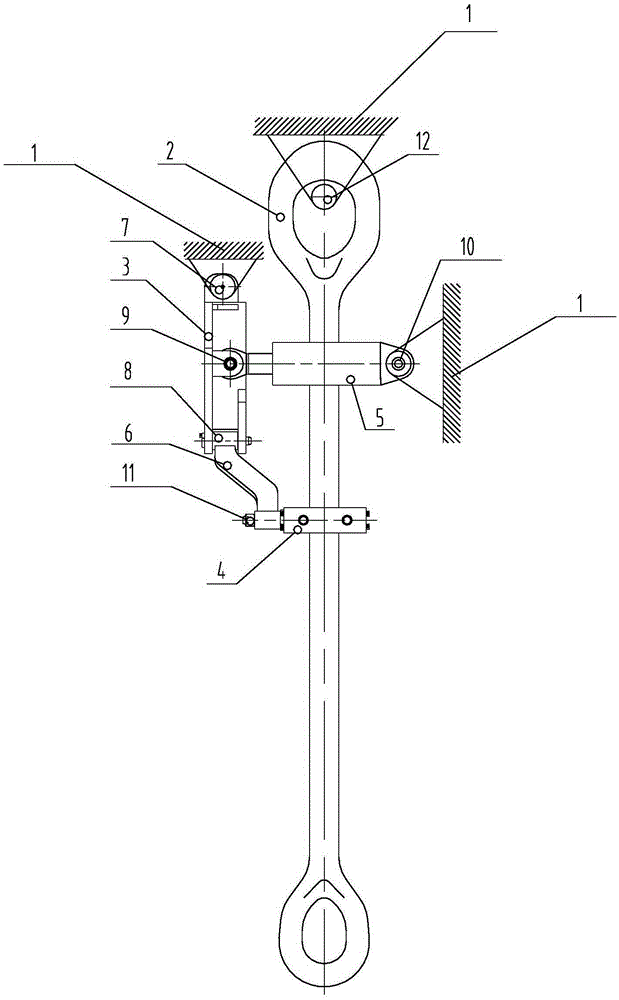
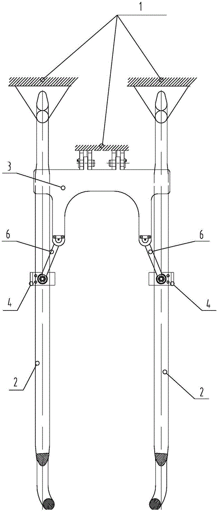
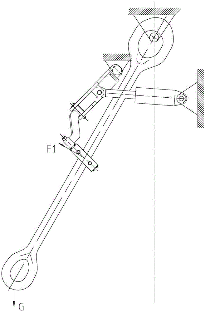
[0036] Such as Figure 1 to Figure 3 As shown, the lifting ring tilting mechanism of this embodiment includes a lifting ring 2, a bracket 3, a hoop 4 and an oil cylinder 5,

[0037] The upper end of the lifting ring 2 is hinged on the top drive body 1 through the sixth pin shaft 12, and the lifting ring 2 can rotate around the sixth pin shaft 12;

[0038] The upper end of the bracket 3 is hinged on the top drive body 1 through the first pin shaft 7, and the bracket 3 can rotate around the first pin shaft 7;

[0039] The lower end of support 3 is connected with connecting rod 6, and the upper end of connecting rod 6 is hinged with support 3 by the second bearing pin 8, and connecting rod 6 can rotate around the second bearing pin 8, and the axis line of the second bearing pin 8 and the first The axis lines of a pin shaft 7 are perpendicular to each other;

[0040] The lower end of connecting rod 6 is equipped with hoop 4, as Figure 4 As shown, the hoop 4 includes a roller b...


PUM


Abstract

The invention discloses a suspension ring tilting mechanism, which belongs to the technical field of oil drilling rig equipment. The lifting ring tilting mechanism of the present invention includes a lifting ring and a driving device. The upper end of the lifting ring is hinged on the top drive body. The driving device drives the hanging ring to rotate around the hinge shaft of the lifting ring and the top drive body. The lifting ring tilting mechanism also includes a bracket, and the upper end of the bracket passes through the first pin The shaft is hinged on the top drive body, and the lower end of the bracket is connected with a hoop; the hoop includes a roller bracket and a roller set in the roller bracket; the part where the hoop passes through the hoop and when the hoop is tilted forward or backward, the hoop passes through the hoop Contact with the roller; the driving device drives the bracket to rotate around the first pin shaft, and the bracket rotates and drives the suspension ring to rotate through the hoop. The lifting ring tilting mechanism of the present invention has lower requirements on the driving device and less investment in equipment; at the same time, since the rollers are in contact with the lifting ring, the safety of the device is good and the installation workload is small. The range of application of the device.

Description

technical field [0001] The invention relates to a suspension ring tilting mechanism, which belongs to the technical field of oil drilling rig equipment. Background technique [0002] The top drive has become the standard equipment of oil drilling rigs, and the automatic pipe handling system equipped on the top drive greatly reduces the labor intensity of workers. As a part of the top drive, the ring tilting mechanism plays an important role. It can lean forward to reach the mouse hole to grab the drill pipe, and lean forward to help the finishing to grab the drill pipe when it is on the second floor platform, which greatly reduces the labor intensity of the workers. [0003] In the prior art, the lifting ring tilting mechanism of the top drive is as Figure 5 , Figure 6 As shown, it includes the lifting ring, the lifting ring holder and the oil cylinder. The upper ends of the lifting ring and the oil cylinder are respectively hinged on the top drive body, the lifting ring...

Claims


Application Information

Patent Timeline
Patent Type & Authority Patents(China)
IPC IPC(8): E21B19/00
Inventor 柴俊卿张芳芳刘宾王翌李龙俞海明姜慧
Owner SICHUAN HONGHUA PETROLEUM EQUIP
Why Eureka
Try Eureka