A multi-degree-of-freedom automatic piling device and piling method

A technology of piling device and degree of freedom, applied in sheet pile wall, construction, infrastructure engineering and other directions, can solve the problems of low piling efficiency, low safety factor, high noise, etc., to improve piling quality, avoid safety accidents, and improve safety. The effect of coefficients

Inactive Publication Date: 2015-10-28
QINGDAO UNIV OF SCI & TECH
View PDF6 Cites 0 Cited by
  • Summary
  • Abstract
  • Description
  • Claims
  • Application Information

AI Technical Summary

Problems solved by technology

[0005] The purpose of the present invention is to overcome the shortcomings of existing piling machines that cannot automatically place wooden piles, cannot guarantee the quality of piling, is inconvenient to use, is too bulky, has high noise, low safety factor, and low piling efficiency, and provides a method that can automatically place wooden piles. Pile driving device with high quality, easy to use, small size, low noise, high safety factor and high piling efficiency

Method used


Image

  • A multi-degree-of-freedom automatic piling device and piling method
  • A multi-degree-of-freedom automatic piling device and piling method

Examples


Embodiment 1

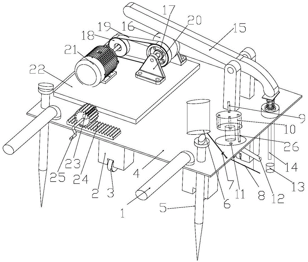
[0025] Such as figure 1 As shown, the multi-degree-of-freedom automatic piling device of the present invention includes a handrail 1, a support column 2, a runner 3, a frame 4, a screw 5, a water tank 6, a switch 7, a water pipe 8, a second handle 9, and a pile through hole 10 , discharge hole 11, stake transition groove 12, positioning tube 13, impact rod 14, lever 15, cam 16, second pulley 17, first pulley 18, flat belt 19, bracket 20, motor 21, support plate 22, sprocket wheel 23, chain 24, first handle 25, stake 26.

[0026]Hold the handrail 1 of the frame 4 to move the automatic piling device to the position where piling is required, and screw the screw 5 into the ground to prevent the piling device from trembling during work and improve safety. Turn on the switch 7 of the water tank 6, and the water pipe 8 will spray water to the ground below the positioning pipe 13, which can reduce the friction between the stake and the ground in the piling process, thereby improving ...

Embodiment 2

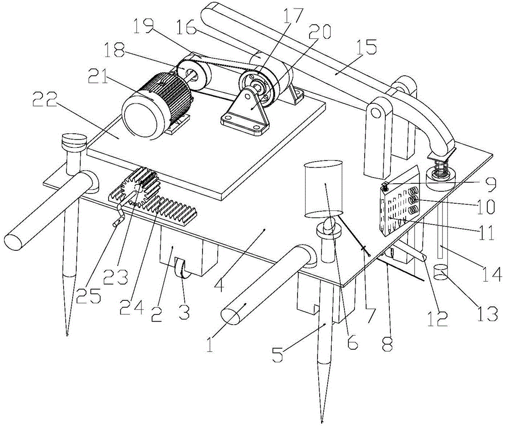
[0028] Such as figure 2 As shown, the multi-degree-of-freedom automatic piling device of the present invention includes a handrail 1, a support column 2, a runner 3, a frame 4, a screw 5, a water tank 6, a switch 7, a water pipe 8, a discharge switch 9, a spring 10, and a wooden pile 11. Pile transition groove 12, positioning pipe 13, impact rod 14, lever 15, cam 16, second pulley 17, first pulley 18, flat belt 19, bracket 20, motor 21, support plate 22, sprocket 23, chain 24, first handle 25.

[0029] Hold the handrail 1 of the frame 4 to move the automatic piling device to the position that needs piling, and screw the screw 5 in the ground to prevent the piling device from shaking during work. Turn on the switch 7 of the water tank 6, and the water pipe 8 will spray water to the ground below the positioning pipe 13, which can reduce the friction between the stake and the ground in the piling process, thereby improving work efficiency. Press down the discharge switch 9 of ...


PUM


Abstract

The invention relates to a multi-freedom-degree automatic piling device and method. The piling device comprises a piling mechanism, a water tank, a rack and a feeder which are arranged above the rack. The piling mechanism comprises a motor, a belt wheel group, a lever and an impacting rod. The motor is connected with the belt wheel group which is connected with the lever, and the lever is connected with the impacting rod. The feeder comprises a cylinder, a feeding hole, a pile transition groove and a location tube. The pile transition groove and the location tube are mounted below the rack, the pile transition groove is disposed between the location tube and the feeding hole, and the location tube is disposed below the impacting rod. The multi-freedom-degree automatic piling device is capable of arranging piles automatically, high in piling quality, convenient to use, small in size and noise, high in safety factor and high in piling efficiency.

Description

technical field [0001] The invention belongs to the field of piling machinery, and in particular relates to a multi-degree-of-freedom automatic piling device and a piling method. Background technique [0002] Pile drivers are widely used in agricultural production, especially when building agricultural greenhouses. In most cases, farmers drive the piles manually with a hammer, or use an electric drill to drill holes in the ground before driving the stakes in. Wooden stakes hammered with a hammer have greater friction with the ground, and the stakes will not be pulled out of the ground when encountering strong winds, but it is labor-intensive for farmers. The labor intensity of drilling piles with an electric drill is small, but the friction between the wooden piles and the ground is small, and the wooden piles are easily pulled out of the ground when encountering strong winds. Some greenhouses need to remove and reinstall wooden piles every year to plant different crops, s...

Claims


Application Information

Patent Timeline
Patent Type & Authority Patents(China)
IPC IPC(8): E02D7/06E02D7/16E02D13/04
Inventor 李利施旭峰汪传生王宇帆鲍晓光
Owner QINGDAO UNIV OF SCI & TECH
Why Eureka
Try Eureka