
Mechanical welding seam tracking device

A tracking device and mechanical technology, applied in the field of weld seam tracking, can solve the problems of large deformation before welding, high manufacturing and maintenance costs, poor flexibility, etc., and achieve the effect of smooth welding, simple structure and cost reduction

Active Publication Date: 2014-08-20
上海气焊机厂有限公司
View PDF9 Cites 17 Cited by
  • Summary
  • Abstract
  • Description
  • Claims
  • Application Information

AI Technical Summary

Problems solved by technology

[0002] In beam and tube plate welded structural parts, there are a large number of fillet welds that need to be welded. Due to structural and process limitations, most of these parts to be welded have large deformation before welding and difficult seam alignment. We must use a seam tracking device To eliminate the welding process error, the existing electric seam tracking device needs to use a sensor to pick up the trajectory signal through the trajectory tracking sensor, and realize the trajectory deviation tracking correction through the controller to control the motor to meet the requirements of tracking welding. The application of sensor automatic control and high-precision mechanical rotation technology is highly specialized, so the application range of this technology is limited, the manufacturing and maintenance costs are also high, and it is susceptible to arc interference; while the traditional mechanical seam tracking device is flexible. Poor, low reliability, straightness deviation needs to be manually adjusted, each welding process needs to be manually moved back and forth for alignment, and the welding track needs to be manually tracked and adjusted continuously, which requires high technical requirements for personnel operation and low efficiency. Well adapted to the process requirements of welding

Method used


Image

  • Mechanical welding seam tracking device
  • Mechanical welding seam tracking device
  • Mechanical welding seam tracking device

Examples


Embodiment Construction

[0021] Embodiments of the present invention are described in detail below in conjunction with accompanying drawings:

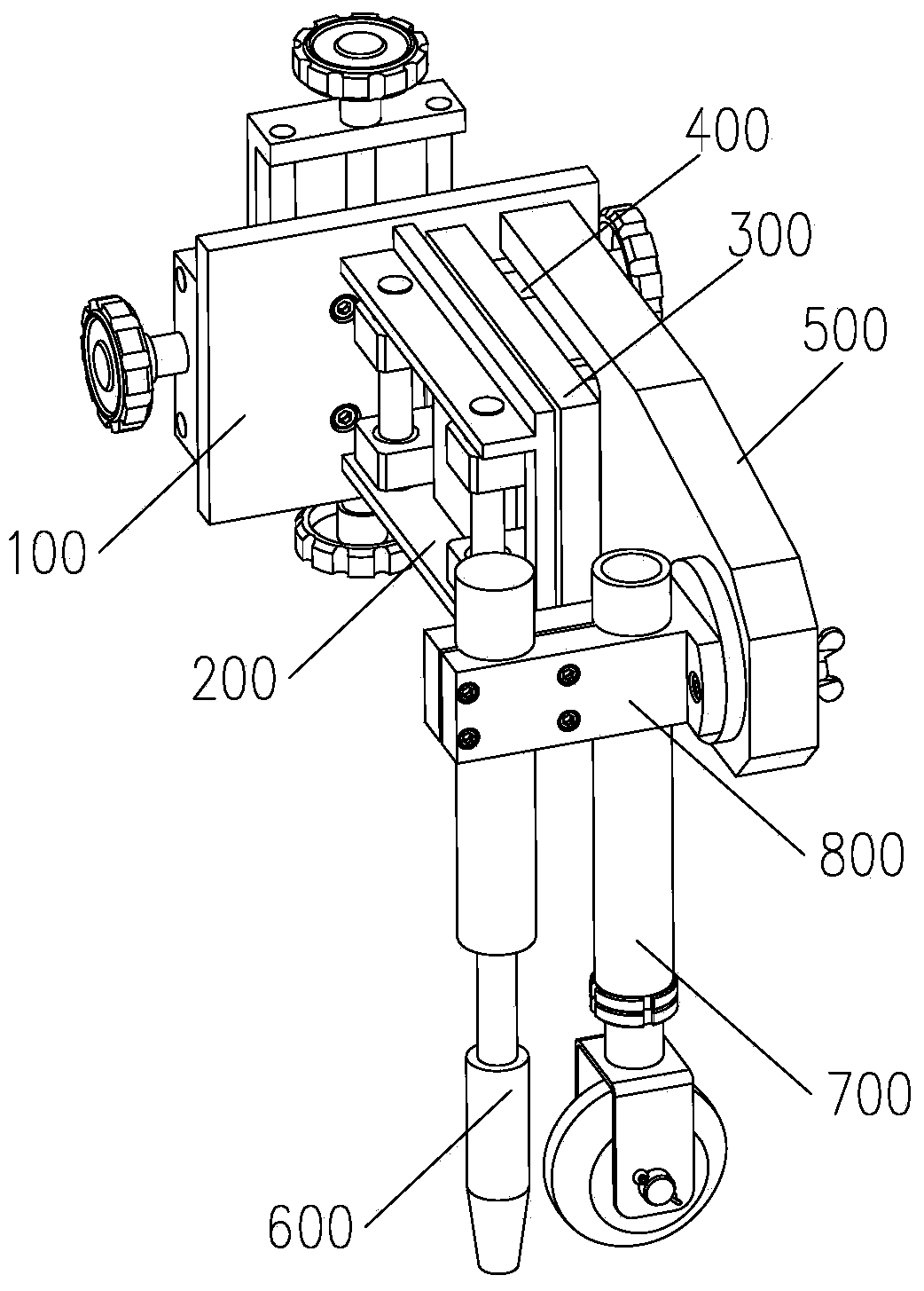
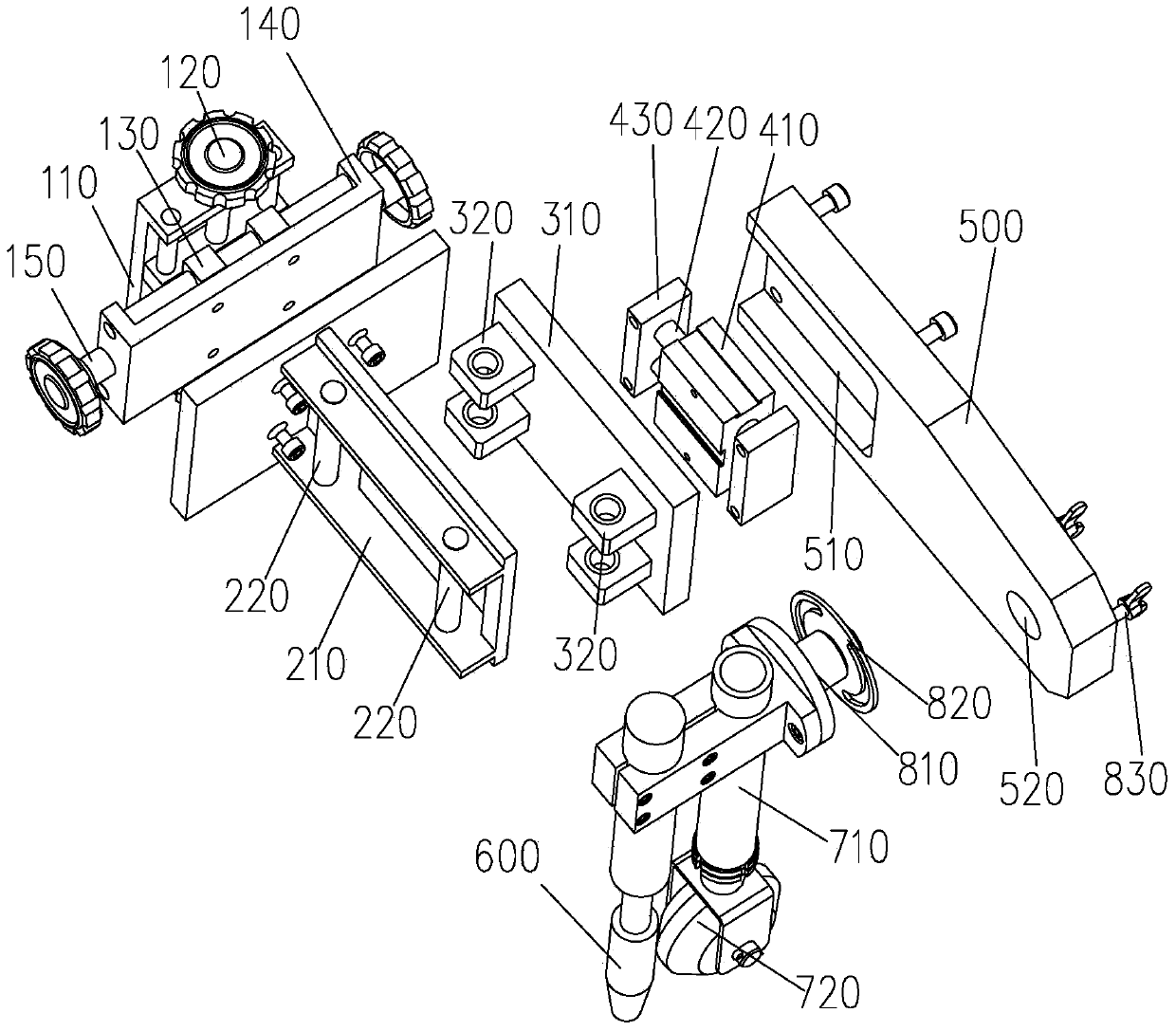
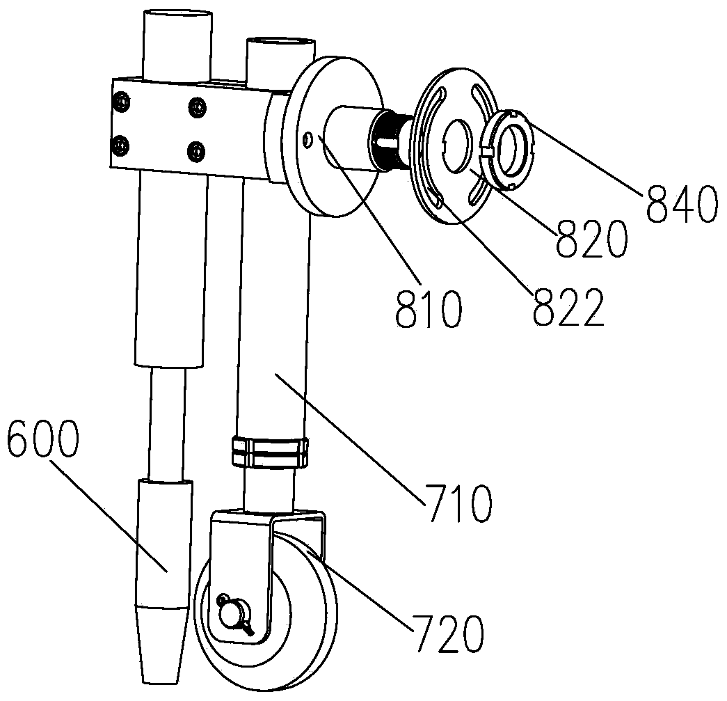
[0022] Such as figure 1 As shown, a mechanical seam tracking device includes a fine-tuning mechanism 100, a guide rod mechanism 200, a guide plate mechanism 300, a horizontal drive mechanism 400, a connecting plate 500, a welding torch 600, a tracking assembly 700, and a steering gear 800. The fine-tuning mechanism 100, the guide plate mechanism 300 is respectively connected with the guide rod mechanism 200, and the guide plate mechanism 300 can move up and down relative to the guide rod mechanism 200, the horizontal drive mechanism 400 is respectively connected with the connecting plate 500, the guide plate mechanism 300, the welding torch 600 and the tracking assembly 700 are installed on the diverter 800 respectively, and the diverter 800 is installed on the connecting plate 500 .

[0023] The mechanical seam tracking device described in this embodiment ha...


PUM


Abstract

The invention discloses a mechanical welding seam tracking device. The mechanical welding seam tracking device comprises a fine adjustment mechanism, a guide rod mechanism, a guide plate mechanism, a horizontal driving mechanism, a connecting plate, a welding gun, a tracking assembly and a steering gear, wherein the fine adjustment mechanism and the guide plate mechanism are respectively connected with the guide rod mechanism, the guide plate mechanism can move up and down relative to the guide rod mechanism, the horizontal driving mechanism is respectively connected with the connecting plate and the guide plate mechanism, the welding gun and the tracking assembly are respectively installed on the steering gear, and the steering gear is installed on the connecting plate. The mechanical welding seam tracking device is simple in structure, no electric sensors need to be arranged, and the cost is effectively reduced; due to the horizontal driving mechanism and the gravity of the mechanical welding seam tracking device, the tracking assembly can make contact with the surface of a workpiece to be welded all the time; due to the guide plate mechanism and the guide rod mechanism which move relative to each other, the mechanical welding seam tracking device is better in flexibility, and the initial position of the welding gun and the initial position of the tracking assembly can be aligned conveniently through the fine adjustment mechanism; due to the steering gear, the angle of the welding gun and the angle of the tracking assembly can be adjusted conveniently.

Description

technical field [0001] The invention relates to seam tracking technology, in particular to a mechanical seam tracking device. Background technique [0002] In beam and tube plate welded structural parts, there are a large number of fillet welds that need to be welded. Due to structural and process limitations, most of these parts to be welded have large deformation before welding and difficult seam alignment. We must use a seam tracking device To eliminate the welding process error, the existing electric seam tracking device needs to use a sensor to pick up the trajectory signal through the trajectory tracking sensor, and realize the trajectory deviation tracking correction through the controller to control the motor to meet the requirements of tracking welding. The application of sensor automatic control and high-precision mechanical rotation technology is highly specialized, so the application range of this technology is limited, the manufacturing and maintenance costs are...

Claims


Application Information

Patent Timeline
IPC IPC(8): B23K9/127
CPCB23K9/127
Inventor 不公告发明人
Owner 上海气焊机厂有限公司
Learn More