Extinguishment transformer

A transformer and refractory technology, applied in the field of transformers, can solve the problems of coil aging, coil heating, heat accumulation, etc.

Inactive Publication Date: 2014-08-13
KUNSHAN DAGONG ELECTRONICS
View PDF5 Cites 6 Cited by
  • Summary
  • Abstract
  • Description
  • Claims
  • Application Information

AI Technical Summary

Problems solved by technology

In order to avoid leakage or other accidents, an insulating pad is usually installed between the magnetic core and the coil frame, but the magnetic core will generate heat during operation, which will cause the aging of the insulating pad, and the coil will also generate heat, and the heat will accumulate, which will cause the coil to age. Causing local fires and safety accidents, such problems have not been solved in the prior art

Method used


Image

  • Extinguishment transformer

Examples


Embodiment Construction

[0017] The present invention will be described in detail below in conjunction with the accompanying drawings and specific embodiments.

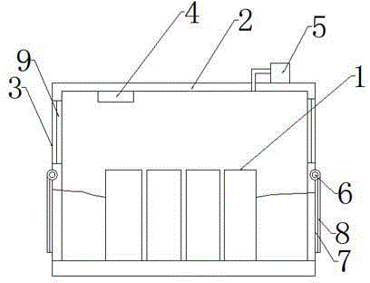
[0018] The fire extinguishing transformer includes: a coil frame 1 for winding coils, a magnetic core placed in the central through hole of the coil frame 1, and also includes: a fire-resistant transformer shell 2, and vents 3 arranged on both sides of the fire-resistant transformer shell 2, which are located at the vents 3, the rotatable and closed assembly of the ventilation opening 3, the temperature sensor 4 located in the fire-resistant transformer shell 2, and the air extraction part placed on the fire-resistant transformer shell 2; as a preference, the air extraction part is connected to the Electric air suction pump 5 in the fire extinguishing transformer. In order to avoid excessive temperature from burning through the shell of the fire-extinguishing transformer and contact with air again, the material used for the fire-resistant tra...


PUM


Abstract

The invention discloses an extinguishment transformer. The extinguishment transformer comprises a coil frame and a magnetic core, wherein the coil frame is wound with a coil, and the magnetic core is placed in a central through hole of the coil frame. The extinguishment transformer further comprises a fireproof transformer casing, ventilation openings arranged on two sides of the fireproof transformer casing, rotatable sealing modules arranged beside the ventilation openings and sealing the ventilation openings, a temperature sensor arranged in the fireproof transformer casing and an air suction part placed on the fireproof transformer casing. When the coil or the magnetic core is overheated and fires caused by coil combustion are caused, the transformer can be sensed and automatically sealed, oxygen in the transformer is sucked away, the effect of extinguishment is achieved, and the extinguishment transformer is good in effect and low in cost.

Description

technical field [0001] An electrical device, especially a transformer. Background technique [0002] A transformer according to the prior art mainly has a form in which a primary coil and a secondary coil are sequentially wound on a single bobbin, and a core is coupled to the bobbin through a through hole of the bobbin. In order to avoid leakage or other accidents, an insulating pad is usually installed between the magnetic core and the coil frame, but the magnetic core will generate heat during operation, which will promote the aging of the insulating pad, and the coil will also generate heat, and the heat will accumulate, which will promote the aging of the coil. Cause local fire, safety accident takes place, prior art has not solved such problem yet. Contents of the invention [0003] In order to solve the deficiencies of the prior art, the purpose of the present invention is to provide a method that can sense and automatically seal the transformer when the coil or the...

Claims


Application Information

Patent Timeline
IPC IPC(8): H01F27/02H01F27/08A62C3/16
Inventor 任育文
Owner KUNSHAN DAGONG ELECTRONICS
Why Eureka
Try Eureka