
Three-frame four-axis inertial platform error calibration method based on navigation datum system

An error calibration and three-frame technology, applied in the field of inertial platforms, can solve problems such as errors, affecting the maneuverability and landing accuracy of missile systems, and having no direct relationship with hexahedrons

Active Publication Date: 2014-08-13
BEIJING INST OF AEROSPACE CONTROL DEVICES
View PDF6 Cites 17 Cited by
  • Summary
  • Abstract
  • Description
  • Claims
  • Application Information

AI Technical Summary

Problems solved by technology

At present, my country's missile-borne three-frame four-axis inertial platform system adopts the assembly benchmark of the platform-hexahedron as the calibration benchmark of the platform, and based on this, the error model of the three-frame four-axis inertial platform is established. But accelerometer and gyroscope data, not directly related to the hexahedron
This determines that the error self-calibration method of the existing model platform in my country not only has fewer error items in the calibration (limited to the zero-order item and first-order item of the gyroscope and accelerometer), but the calibration state of the platform is inconsistent with the actual use state, resulting in low calibration accuracy. , and the installation error of the accelerometer can only be calibrated separately by external high-precision optical equipment using complex methods, while the installation error of the gyroscope is too complicated due to the dependence on the equipment, which leads to engineering errors to calibrate it out
Therefore, this traditional hexahedron-based inertial platform system modeling method seriously affects the use accuracy of the inertial platform, thereby affecting the maneuverability and landing accuracy of the missile system

Method used


Image

  • Three-frame four-axis inertial platform error calibration method based on navigation datum system
  • Three-frame four-axis inertial platform error calibration method based on navigation datum system
  • Three-frame four-axis inertial platform error calibration method based on navigation datum system

Examples


Embodiment Construction

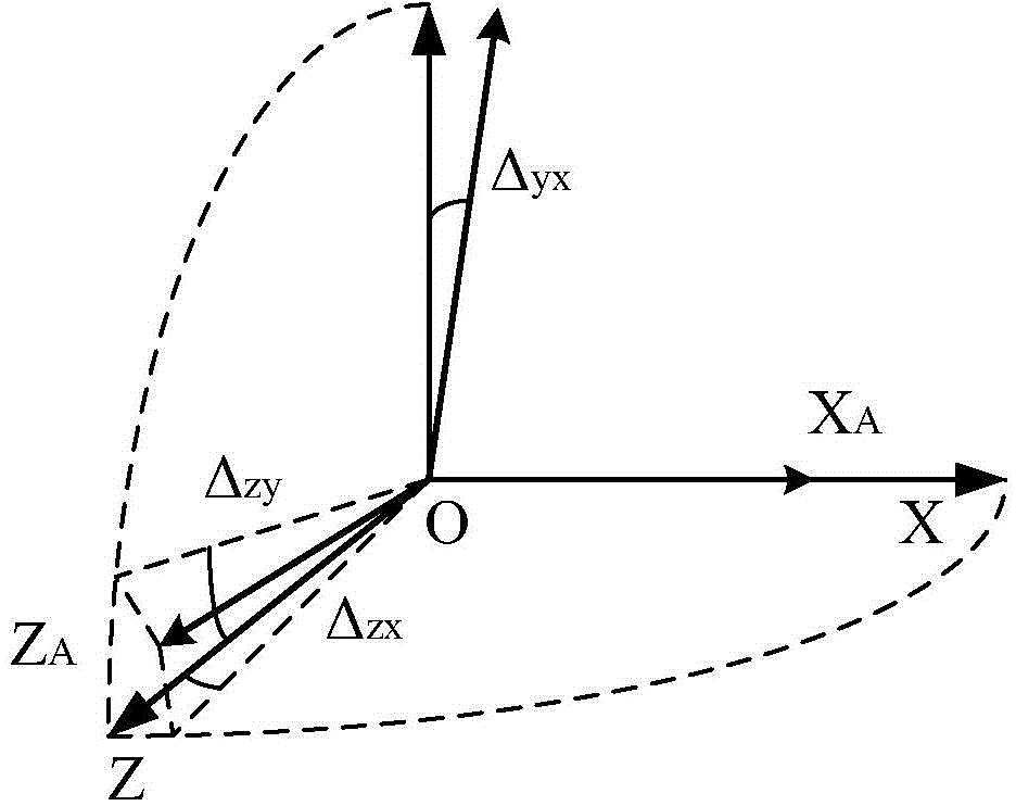
[0050] Such as figure 1 Shown, the concrete realization steps of the present invention are as follows:

[0051] (1) Establishment of the reference coordinate system

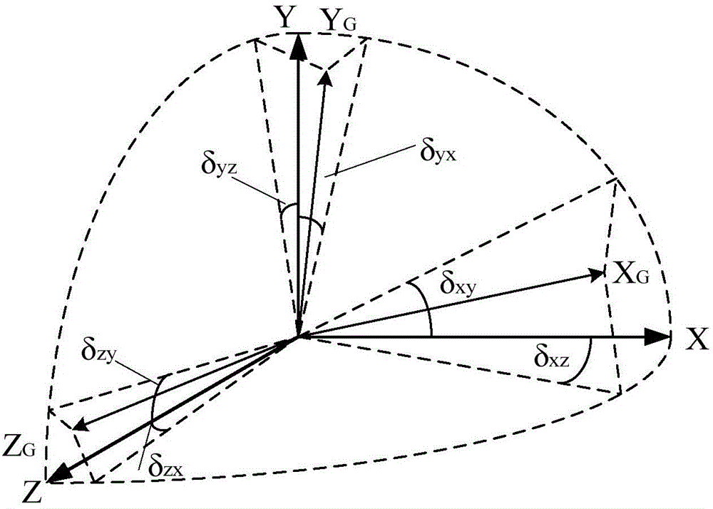
[0052] Breaking through the traditional modeling idea, according to the actual use of the three-frame four-axis inertial platform, the X accelerometer input axis actually used in the navigation process is used as the reference axis to establish the reference coordinate system OXYZ of the three-frame four-axis inertial platform system, as shown in figure 2 Shown: the OX axis coincides with the input axis of the X accelerometer, the OY axis is located in the plane determined by the OX axis and OYA, and is perpendicular to the OX axis, and the OZ axis is determined by the right-hand rule.

[0053] Since the actual navigation system rather than the optical reference is used as the reference coordinate system for calibration, this method can make the installation error calibration of the gyroscope and accelerometer ...


PUM


Abstract

A three-frame four-axis inertial platform error calibration method based on a navigation datum system comprises the following steps: with an X accelerometer input shaft as a datum axis, establishing a datum coordinate system OXYZ calibrated by a platform system; based on the datum coordinate system, establishing a platform system accelerometer output error model including an accelerometer installation error, a gyroscope drift error model and a frame angle output error model; and then according to the above three models, completing a calibration work of a three-frame four-axis inertial platform. Relying on a high-precision accelerometer on the platform, the navigation method is adopted to achieve self-calibration, and thus the calibration method is greatly simplified, the calibration cost is reduced, and the calibration accuracy is improved.

Description

technical field [0001] The invention relates to an error calibration method for a three-frame four-axis inertial platform based on a navigation reference system, and belongs to the technical field of inertial platforms. Background technique [0002] The pre-launch self-calibration technology of the three-frame four-axis inertial platform uses the inertial instrument's primary stability instead of the sequential stability to reduce random errors. Before the missile is launched, the error model of the platform is self-calibrated at the launch site once, and the error coefficients are separated. The real-time compensation used for the computer flight guidance on the missile is a very economical and effective technical way to improve the maneuverability and landing accuracy of the missile weapon system. [0003] The establishment of the reference coordinate system for the error calibration of the inertial instrument of the three-frame four-axis inertial platform system is the ba...

Claims


Application Information

Patent Timeline
IPC IPC(8): G01C25/00
CPCG01C21/18G01C25/005
Inventor 刘静朱志刚王汀闫禄郭宗本
Owner BEIJING INST OF AEROSPACE CONTROL DEVICES
Learn More