Equipment for lifting and positioning objects

A technology for equipment and objects, which is applied in the field of equipment for lifting and positioning objects, and can solve problems such as hindering the precise positioning of objects and equipment slippage

Active Publication Date: 2016-02-03
BDT MEDIA AUTOMATION
View PDF14 Cites 0 Cited by
  • Summary
  • Abstract
  • Description
  • Claims
  • Application Information

AI Technical Summary

Problems solved by technology

[0005] However, problems can also arise with known eddy current attractors: Objects with curved geometry or rough surfaces slip relative to the device during lifting or holding, thus preventing precise positioning of the object

Method used


Image

  • Equipment for lifting and positioning objects
  • Equipment for lifting and positioning objects
  • Equipment for lifting and positioning objects

Examples


Embodiment Construction

[0087] In the various figures, identical reference numbers designate identical or functionally identical components, wherein for the sake of clarity not all reference numbers are indicated in all figures.

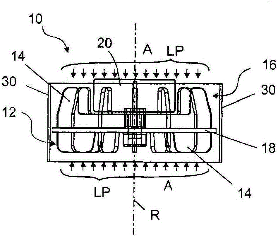
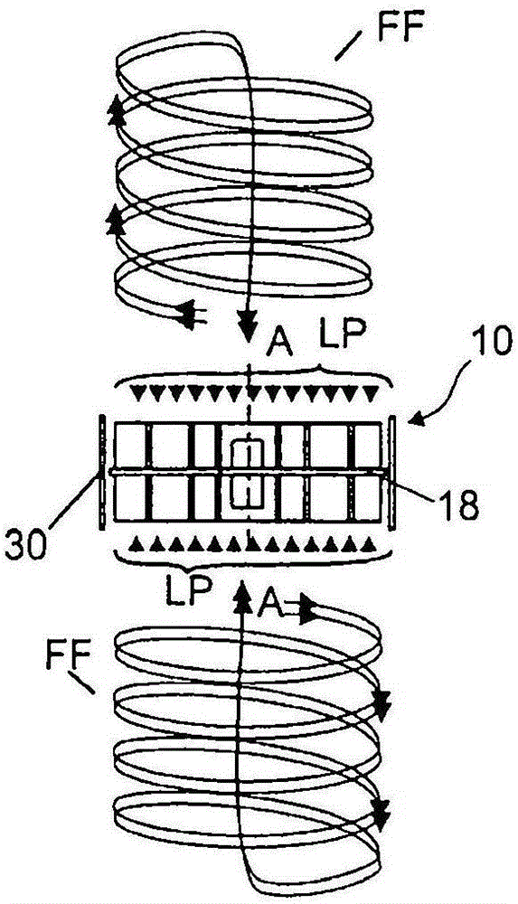
[0088] figure 1 and 2 The vortex attractor 10 is shown with a lower impeller 12 driven by an electric motor 20 . The lower impeller 12 has a partition element 18 driven by an electric motor 20 and a plurality of radially extending blades 14 on the partition element 18 , which are arranged substantially vertically on the partition element 18 . The blade 14 rotates about the axis R of rotation. In one embodiment, a similarly constructed upper impeller 16 with blades 14 is arranged on the opposite side of the separating element 18 . In one embodiment, one of the two impellers 12 , 16 , preferably the upper impeller 16 is used to cool the electric motor 20 . The separating element 18 may be arranged symmetrically between the upper impeller 16 and the lower impeller 12, howe...


PUM


Abstract

The invention relates to a device (10) for lifting and positioning objects, the device having first means for generating a negative pressure by means of a cyclone to attract objects, wherein said first means are arranged inside a housing, the The housing has a suction opening and the housing has at least one friction element which at least partially covers the suction opening.

Description

technical field [0001] The invention relates to a device for lifting and positioning objects. Background technique [0002] It is known that devices for lifting and positioning objects in space are based on suction heads, such as elastic suction cups, connected to a pump or the like, in order to hold the objects with the suction head by negative pressure and friction and to be able to Hang it on the suction head and move it freely in space. Especially for larger or flat items such as plastic plates, metal plates or paper often require multiple suction heads in order to be able to hold the object during movement. During the movement, relative movements between the object and the suction head must be reliably avoided in order to enable precise positioning of the object following the movement. [0003] When using known suction heads on geometrically incorrect objects, objects with rough surfaces, or greasy, dirty or otherwise soiled objects, there is a sudden loss of contact ...

Claims


Application Information

Patent Timeline
Patent Type & Authority Patents(China)
IPC IPC(8): B66C1/02B65G47/91B65H3/08
CPCB65G47/91B66C1/0212B65H3/0816B65H2404/5213B65H2404/5311B65H2406/36625B65H2511/214B65H2515/20B65H2220/01B65H2220/11B65H2220/02B25J15/0616
Inventor P·X·基尔尼
Owner BDT MEDIA AUTOMATION
Why Eureka
Try Eureka