
Method for manufacturing capacitance type micro-silicon microphone

A silicon microphone and manufacturing method technology, applied in electrical components, sensors, etc., can solve the problems of small effect, buckling of the vibrating body, complicated processing technology, etc., and achieve the effect of reducing the impact, reducing the volume, and improving the sensitivity

Active Publication Date: 2014-08-06
MEMSENSING MICROSYST SUZHOU CHINA
View PDF4 Cites 3 Cited by
  • Summary
  • Abstract
  • Description
  • Claims
  • Application Information

AI Technical Summary

Problems solved by technology

Residual stress has a great influence on the characteristics of the capacitive micro-silicon microphone, and even makes it fail to work
A large residual tensile stress will significantly reduce the mechanical sensitivity of the vibrating body, and the mechanical sensitivity of the vibrating body is proportional to the key index of the capacitive micro-silicon microphone—sensitivity, so a large residual stress will reduce the sensitivity of the capacitive micro-silicon microphone
In addition, the large residual compressive stress may cause the vibrating body to buckle, thereby rendering the capacitive microsilicon microphone ineffective
[0005] Improving the sensitivity of the capacitive microsilicon microphone can reduce the residual stress of the vibrating body by improving the preparation method - deposition, or using some additional processes such as annealing, etc., but this method has little effect on reducing the residual stress, and repeated The performance is not good, and the realization is relatively complicated; another important way is to optimize the design of the vibrating body structure to make the mechanical sensitivity of the vibrating body, but the processing technology in the existing technology is complicated

Method used


Image

  • Method for manufacturing capacitance type micro-silicon microphone
  • Method for manufacturing capacitance type micro-silicon microphone
  • Method for manufacturing capacitance type micro-silicon microphone

Examples


Embodiment Construction

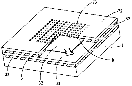
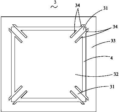
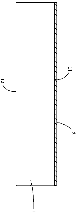
[0033] See figure 1 and Figure 12 The capacitive microsilicon microphone in one embodiment of the present invention includes a substrate 1 with a front surface 11 and a back surface 12, a movable sensitive layer 3 arranged on the front surface 11 of the substrate 1 and having a conductive function, and arranged on the movable sensitive layer 3 And the back electrode plate 72 with conductive function, the first supporting part 23 arranged between the front surface 11 of the substrate 1 and the movable sensitive layer 3 and used to support the movable sensitive layer 3, the first supporting part 23 arranged between the movable sensitive layer 3 and the back Between the pole plates 72 and used to support the second support portion 62 of the back pole plate 72, several metal pads 14 respectively formed on the movable sensitive layer 3 and the back pole plate 72, and formed on the back pole plate 72 and the back pole plate 72 The cavity 8 between the movable sensitive layers 3 . ...


PUM


Abstract

The invention relates to a method for manufacturing a capacitance type micro-silicon microphone. The method includes the following steps: S1, providing a substrate, S2, depositing insulating materials on the front face of the substrate to form a first insulating layer, S3, depositing electric conduction matters on the first insulating layer to form a movable sensitive layer, and forming a plurality of narrow grooves in the movable sensitive layer to define an oscillating body, a frame arranged on the periphery of the oscillating body in a surrounding mode and a beam for connecting the frame and the oscillating body, S4, depositing insulating materials on the movable sensitive layer to form a second insulating layer, and depositing electric conduction matters on the second insulating layer to manufacture a back counter electrode, S5, forming a plurality of sound holes in the back counter electrode, S6, forming a metal pressure welding point, S7, forming a back cavity in the substrate, wherein the back cavity extends from the back face of the substrate to the front face of the substrate to penetrate through the substrate, and S8, removing part of the first insulating layer to enable the oscillating body to be exposed out of the back face of the substrate and enable the oscillating body and the beam to be suspended, and removing the part, among the oscillating body, the beam and the back counter electrode, of the second insulating layer.

Description

technical field [0001] The invention relates to a method for manufacturing a capacitive micro-silicon microphone, which belongs to the field of micro-electro-mechanical systems. Background technique [0002] MEMS technology is a high-tech that has developed rapidly in recent years. It adopts advanced semiconductor manufacturing technology to realize the batch manufacturing of MEMS devices. obvious advantage. In the market, the main application examples of MEMS devices include pressure sensors, accelerometers and silicon microphones. [0003] The automatic surface mount process for assembling the microphone to the circuit board needs to experience high temperature. The traditional electret microphone (ECM) will leak charge at high temperature, causing the ECM to fail. Therefore, the assembly of the ECM can only be assembled by hand. Capacitive micro-silicon microphones can withstand high temperatures and can be automatically assembled using surface mount technology. In addi...

Claims


Application Information

Patent Timeline
Patent Type & Authority Applications(China)
IPC IPC(8): H04R31/00
Inventor 李刚胡维梅嘉欣
Owner MEMSENSING MICROSYST SUZHOU CHINA
Learn More