
Camera head and optical imaging lens

An optical imaging lens and imaging technology, used in optics, optical components, instruments, etc., can solve the problem of small field of view, and achieve the effect of expanding the shooting angle and good optical performance

Active Publication Date: 2014-08-06
GENIUS ELECTRONICS OPTICAL XIAMEN
View PDF5 Cites 11 Cited by
  • Summary
  • Abstract
  • Description
  • Claims
  • Application Information

AI Technical Summary

Problems solved by technology

For example, Taiwan patent 201111828 discloses an infrared imaging lens group, but the field of view is about 35 degrees, and the field of view is small

Method used


Image

  • Camera head and optical imaging lens
  • Camera head and optical imaging lens
  • Camera head and optical imaging lens

Examples


Embodiment Construction

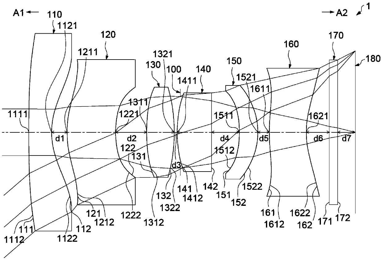
[0108] In order to further illustrate various embodiments, the present invention provides description drawings. These drawings are part of the disclosure content of the present invention, which are mainly used to illustrate the embodiments, and can explain the operating principles of the embodiments in conjunction with the relevant descriptions in the description. With reference to these contents, those skilled in the art should understand other possible implementations and advantages of the present invention. Components in the figures are not drawn to scale, and similar component symbols are generally used to denote similar components.

[0109] The term "a lens has positive refractive power (or negative refractive power)" in this specification means that the lens has positive refractive power (or negative refractive power) in the area near the optical axis. "The object side (or image side) of a lens includes a convex surface (or concave surface) in a certain area" means that...


PUM


Abstract

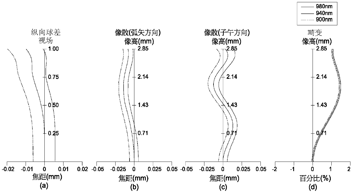
The invention relates to a camera head and an optical imaging lens thereof. The optical imaging lens comprises six lenses, wherein a first lens has negative refractive indexes; an image side surface of a second lens is provided with a concave surface which is positioned on an area nearby a circumference; an object side surface of a third lens is provided with a convex surface which is positioned on an area nearby an optical axis; an object side surface of a fourth lens is provided with a convex surface which is positioned on an area nearby the circumference; an image side surface of a fifth lens is provided with a convex surface which is positioned on an area nearby the optical axis; and an image side surface of the six lens is provided with a concave surface which is positioned on an area nearby the optical axis. The camera head comprises a shell and an image module. The image module comprises the optical imaging lens, a lens cone, a module rear seat unit and an image sensor. The shooting angle can be effectively expanded by controlling arrangement of concave and convex curved surfaces of the lenses; and the optical performance is high.

Description

technical field [0001] The present invention relates to an imaging device and its optical imaging lens, and in particular to an imaging device using a six-lens lens and its optical imaging lens. Background technique [0002] In recent years, the scope of application of small photographic devices has become wider and wider, gradually expanding from portable electronic devices such as mobile phones to interactive electronic devices, such as: game consoles, or environmental monitoring, video recording devices or vehicle monitoring devices, such as : driving record green photography or reversing camera and other related fields, and as modern people have higher requirements for paired driving safety and imaging quality, such devices generally need to provide good imaging performance, and also need to design a fairly wide-angle shooting Angle and night vision capability. Therefore, in terms of optical characteristics, it is necessary to expand the field of view, and the aperture ...

Claims


Application Information

Patent Timeline
IPC IPC(8): G02B13/00G02B13/18
Inventor 许圣伟唐子健叶致仰
Owner GENIUS ELECTRONICS OPTICAL XIAMEN
Learn More