Automatic screw filling machine

A filling machine and fully automatic technology, which is applied to screwdrivers, wrenches, manufacturing tools, etc., can solve the problems of low reliability of mechanized operation, troublesome adjustment of screw size, and low efficiency during use, and achieve simple structure, high automation efficiency, and easy processing convenient effect

Inactive Publication Date: 2016-06-01
孙代明
View PDF7 Cites 0 Cited by
  • Summary
  • Abstract
  • Description
  • Claims
  • Application Information

AI Technical Summary

Problems solved by technology

The disadvantages of this method are 1. Huge volume, 2. Complex structure, 3. It requires a large number of circuits, resulting in high price. 4. It is very troublesome to adjust the screw size.
[0004] 2. The automatic screw row machine of Japanese technology uses the motor to drive the impeller to bring the screws to the guide rail, and uses an electric brush to brush off the screws in different directions on the guide rail, but it also has the following disadvantages: 1. Adjusting the screw size requires mechanical adjustment It can only be adjusted after the principle is very clear, otherwise it cannot be used normally after adjustment; 2. The reliability of mechanized operation is low, and the efficiency is low when used. wasting a lot of time

Method used


Image

  • Automatic screw filling machine
  • Automatic screw filling machine
  • Automatic screw filling machine

Examples


Embodiment

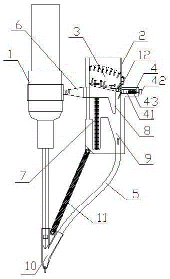
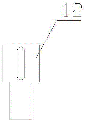
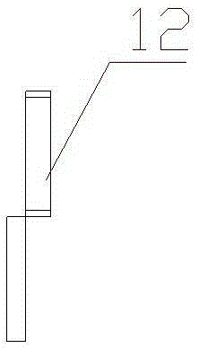
[0024] Example: see figure 1 , figure 2 as well as image 3 , a fully automatic screw filling machine, comprising an electric batch 1 and a screw filling device, the screw filling device comprising a screw storage box 2, a screw arrangement clamp 3, a material distribution clamp 4 and a screw conveying pipeline 5; the specific implementation is, in the screw The storage box 2 is provided with a box cover, which can close the screw storage box 2 .

[0025] The upper part of the screw storage box 2 has a storage cavity, and the side of the storage cavity close to the electric batch 1 is provided with a chute in the vertical direction. The upper edge of the screw arrangement clamp 3 is arc-shaped, and one end close to the chute is higher than the other end, and a screw arrangement groove is provided on the upper edge of the screw arrangement clamp 3 (along its length direction), so that the screws Under the action of gravity, it can slide freely along the chute. The screw ar...


PUM


Abstract

The invention discloses a full-automatic screw filling machine which comprises an electric screw driver and a screw filling device. The screw filling device comprises a screw storage box, a screw arraying clip, a material dividing clip and a screw conveying pipeline. A storage cavity is formed in the upper portion of the screw storage box, the screw arraying clip is placed in the storage cavity, a sliding plate is arranged at the end, close to a sliding groove, of the screw arraying clip, and the sliding plate penetrates out of the screw storage box from the sliding groove and then is fixedly connected with a pressing cap of the electric screw driver. The material dividing clip is arranged on the side, far away from the sliding groove, of the screw storage box. One end of the screw conveying pipeline is connected with a screw conveying channel, and the other end of the screw conveying pipeline is connected with a screw output head and is connected with a cutter head of the electric screw driver through the screw output head. The bottom of the screw storage box is connected with the screw output head through a fixing rod. The full-automatic screw filling machine is simple in structure, capable of effectively improving operation efficiency, capable of conducting free adjusting according to the sizes of screws, convenient to use, and meanwhile lower in production cost.

Description

technical field [0001] The invention relates to a screw loading mechanism, in particular to an automatic screw loading machine. Background technique [0002] Screws are mainly used for fixing between two objects, and are widely used in industrial production, processing and life. However, during the installation process, the screw needs to be placed in a designated position or absorbed by a magnetic screwdriver bit, and then operated, resulting in a very slow operation speed and low efficiency. Therefore, someone has designed a loading machine for automatically loading screws. The current screw loading machines mainly include the following two types: [0003] 1. Use the vibrating plate to vibrate the messy screws (rivets) and use pneumatic or electric parts to send them to the hand-held electric screwdriver with compressed air. The disadvantages of this method are 1. bulky, 2. complex structure, 3. a large number of circuits are required and the price is expensive, and 4. i...

Claims


Application Information

Patent Timeline
Patent Type & Authority Patents(China)
IPC IPC(8): B25B23/04
CPCB25B23/04B25B23/08
Inventor 孙代明
Owner 孙代明
Why Eureka
Try Eureka