
Manhole door sealing structure of dust removal device

A dust removal device and sealing structure technology, which is applied in the direction of sealing devices, windows/doors, building components, etc., can solve the problems of difficult to meet the sealing effect, waste of resources, complex structure, etc., achieve excellent sealing effect, save manufacturing costs and resources, The effect of simplifying the structure

Inactive Publication Date: 2015-09-30
常熟中材装备环保输送机械有限公司
View PDF6 Cites 0 Cited by
  • Summary
  • Abstract
  • Description
  • Claims
  • Application Information

AI Technical Summary

Problems solved by technology

Therefore, if the excellent sealing effect cannot be realized between the manhole door and the dust removal box body, then the aforementioned factors affecting the stable operation of the dust removal device cannot be avoided.
[0003] In the prior art, single-channel seals are generally used for manhole doors of dust removal devices operating under high negative pressure conditions. Although single-channel seals have the advantages of simple structure, they are difficult to meet the sealing effect expected by the industry
[0004] In the published Chinese patent literature, it can be seen that the technical information of the manhole door structure of the dust removal device is typical, such as the "electrical dust removal double-layer square manhole door sealing device" recommended by the authorized announcement number CN201891355U. Inner door and outer door are set at the entrance of the dust removal box, that is, the manhole inspection opening. The inner door forms a seal with the manhole inspection opening through the inner door sealing ring (the patent is called a single-channel sealing line sealing ring for the inner door), and the outer door passes through the outer door. The door sealing ring (the patent is called the outer door double-channel sealing line sealing ring) forms a seal with the manhole inspection port. This patented scheme can objectively reflect the technical effects recorded in paragraphs 0008 to 0012 of its manual, but it has the following shortcomings: First, Because this patent solution is aimed at the dust removal box body that only needs one manhole inspection port, that is, the electrostatic precipitator suitable for the electric power industry, there is no possibility for the aforementioned pumping bag type bag dust removal device that needs to be provided with many manhole doors. The significance of reference; secondly, if the manhole door on the top of the dust removal box of the upper shaft bag type bag type dust removal device is designed as an inner and outer door structure by referring to the enlightenment of this patent, it will not only cause complicated structure and waste of resources, And it is inconvenient in use, because the manhole door on the top of the dust removal box of the upper-pump type bag type dust collector is usually a non-door shaft structure. The so-called non-door shaft structure refers to the manhole door and the dust box body There is no pivotal connection relationship, and the patented solution, whether it is the inner door or the outer door, is pivotally connected to the dust box body through their respective hinges; thirdly, due to the patented inner door sealing ring and outer door sealing ring The structure matched with the inner and outer doors is unreasonable, so the overall labyrinth sealing relationship cannot be formed, and the sealing effect of the manhole part cannot meet the desired requirements; Fourth, due to the sealing ring, especially the outer door sealing ring The structure is complicated and it is a non-standard product, so it is difficult to obtain from commercial channels

Method used


Image

  • Manhole door sealing structure of dust removal device
  • Manhole door sealing structure of dust removal device

Examples


Embodiment Construction

[0020] In order to enable the examiners of the patent office, especially the public, to understand the technical essence and beneficial effects of the present invention more clearly, the applicant will describe in detail the following in the form of examples, but none of the descriptions to the examples is an explanation of the solutions of the present invention. Any equivalent transformation made according to the concept of the present invention which is merely formal but not substantive shall be regarded as the scope of the technical solution of the present invention.

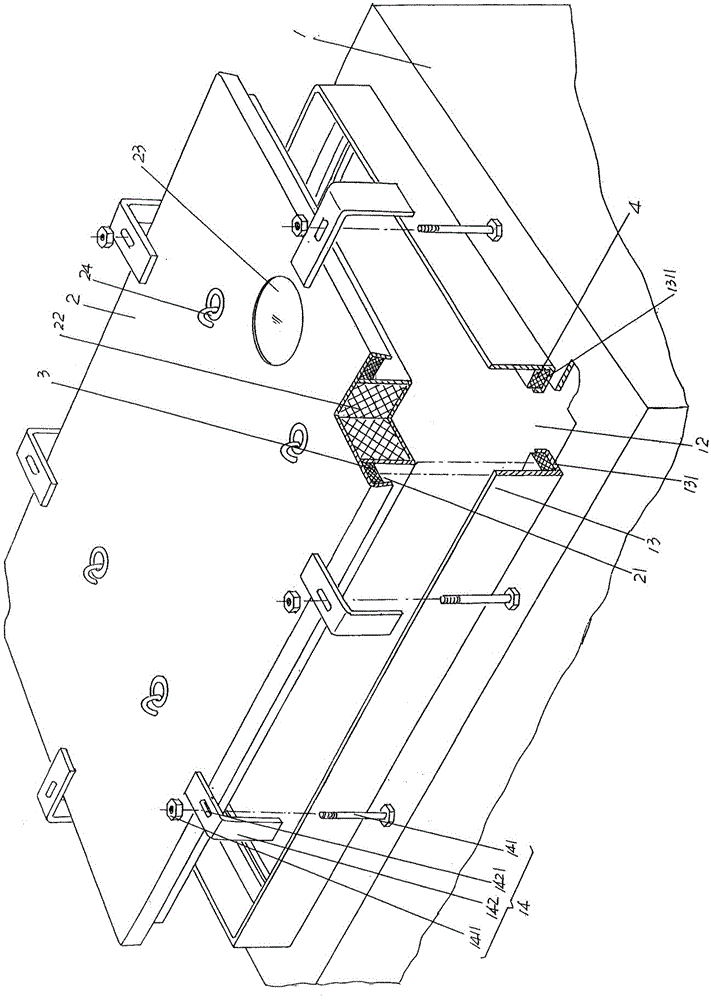
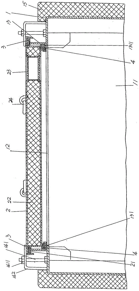
[0021] See figure 1 and figure 2 , a dust removal box body 1 and manhole door 12 are provided, at the top of the dust removal box body 1, there is formed a manhole 12 for inspection personnel to enter the dust removal box body cavity 11 of the dust removal box body 1 to perform maintenance . Along with the variation of the specification of dust removal box casing 1, the quantity of the manhole 12 that offe...


PUM


Abstract

A manhole door sealing structure of a deduster belongs to the technical field of industrial dedusting facilities. The deduster comprises a dedusting box body and a manhole door; a manhole port is formed in the top of the dedusting box body; the manhole door sealing structure comprises a manhole port seal ring and a manhole door seal ring; the manhole door sealing structure is characterized in that a manhole seal ring seat is fixed at the top of the dedusting box body; the lower part of the manhole port seal ring forms a manhole port seal ring support flange; the manhole port seal ring is arranged at one upward side of the manhole port seal ring support flange; a manhole door seal ring embedding cavity is formed at one upward side of the manhole door; the manhole door seal ring is arranged in the manhole door seal ring embedding cavity; as the manhole door seal ring and the upper surface of the manhole port seal ring seat are in contact with each other, and the peripheral edge of the bottom of the manhole door and the manhole port seal ring are in contact with each other, the manhole door seal ring, the manhole port seal ring seat and the manhole port seal ring jointly form dual sealing. The structure is simplified, the cost is reduced, the sealing effect is excellent, and the manhole door sealing structure is convenient to select without nitpicking.

Description

technical field [0001] The invention belongs to the technical field of industrial dust removal facilities, and in particular relates to a manhole door sealing structure of a dust removal device. Background technique [0002] The air leakage rate is an important index to consider the dust removal device. For example, the electric power industry standard in my country stipulates that the air leakage rate of the electrostatic precipitator should be less than 3%. As far as the up-drawing bag type dust removal device is concerned, the air leakage rate has a direct impact on the filtering wind speed of the dust removal device, equipment resistance and the stable operation of the entire dust removal system. With the continuous expansion of the specifications of the dust removal device, especially because the top-pumping bag type bag dust removal device needs to replace the filter bag on the top of the dust removal box, it is necessary to install a number of manhole doors on the to...

Claims


Application Information

Patent Timeline
Patent Type & Authority Patents(China)
IPC IPC(8): E06B5/00E06B7/16
Inventor 王爱琴王惠东张晓梅
Owner 常熟中材装备环保输送机械有限公司
Learn More