Textile humidifying device

A humidification device and textile technology, applied in textiles and papermaking, etc., can solve the problems of increasing production cost, investment and operation cost, and achieve the effect of low cost and simple structure

Active Publication Date: 2014-07-30
GUANGDONG FORWARD DENIM
View PDF6 Cites 4 Cited by
  • Summary
  • Abstract
  • Description
  • Claims
  • Application Information

AI Technical Summary

Problems solved by technology

[0003] At present, the central air-conditioning spray room is widely used as the humidification method, and its investment and operation costs are relatively high, which greatly increases the production cost.

Method used


Image

  • Textile humidifying device

Examples


Embodiment Construction

[0014] The present invention will now be further described in detail in conjunction with the accompanying drawings and embodiments. These drawings are all simplified schematic diagrams, only illustrating the basic structure of the present invention in a schematic manner, so it only shows the composition related to the present invention.

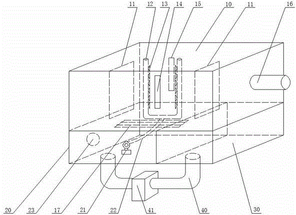
[0015] like figure 1 As shown, a humidifying device for textiles includes a spray chamber 10. Two facing water baffles 11 are arranged in the spray chamber 10. A spraying device is arranged between the two water baffles 11. The spraying device includes a U-shaped water spray Pipe 12, spray pipe 12 both sides are provided with several spray nozzles 13 towards its inner side, spray chamber 10 two opposite side walls are respectively provided with the entrance 14 for textiles to be transported between the water spray pipe 12, and from The outlet 15 that passes out of the spray chamber 10 is provided with an air introduction pipe 16 on the other ...


PUM


Abstract

The invention relates to a textile humidifying device, which comprises a spraying chamber, wherein two opposite water blocking plates are arranged in the spraying chamber, a spraying device is arranged between the two water baffle plates, the spraying device comprises a U-shaped water spraying pipe, a plurality of spray nozzles spaying towards the inner side of the water spraying pipe are arranged at the two sides of the water spraying pipe, an inlet used for conveying textile to a position between the water spraying pipe and an outlet used for conveying out the textile from the spraying chamber are respectively formed in the two opposite side walls of the spraying chamber, and an air introducing pipe is arranged on the other side wall of the spraying chamber. The textile humidifying device has the advantages that the structure is simple, the textile passes between the U-shaped water spray pipe, humid air in the spraying chamber realizes all-around contact with the textile, the goal of humidifying the textile is reached, simplicity is realized, the operation is easy, and in addition, the cost is lower.

Description

technical field [0001] The invention relates to a spraying device, in particular to a device for spraying textiles. Background technique [0002] Humidity conditions are closely related to the textile process. The textile industry uses fiber raw materials. Under different humidity conditions, their physical and mechanical properties (such as moisture regain, strength, elongation, softness and conductivity, etc.) will change. Different degrees of change, such as cotton fiber, when the relative humidity is 60%-70%, the dry state of the fiber's strong arm can be increased by about 50%, because the cotton fiber after moisture absorption, due to the increase in the distance between molecules, the external force Relative displacement will occur under the action of the relative humidity, so the elongation of the fiber increases with the rise of the relative humidity. Similarly, the humidity of semi-finished textiles woven from fiber raw materials is also important before subsequen...

Claims


Application Information

Patent Timeline
IPC IPC(8): D01H13/30
Inventor 庄郁峰
Owner GUANGDONG FORWARD DENIM
Why Eureka
Try Eureka